Pneumatic tire and producing method thereof

A technology for a pneumatic tire and a manufacturing method, which is applied to the reinforcement layer, tire parts, tires and other directions of a pneumatic tire, can solve the problems of low productivity, complex manufacturing process and manufacturing equipment, etc., and achieves reduced stretching, excellent uniformity, The effect of preventing a decrease in productivity

Inactive Publication Date: 2006-05-17
SUMITOMO RUBBER IND LTD
View PDF1 Cites 14 Cited by
  • Summary
  • Abstract
  • Description
  • Claims
  • Application Information

AI Technical Summary

Problems solved by technology

Manufacture of such a carcass ply makes the manufacturing process and manufacturing equipment complicated, and the productivity is low

Method used


Image

  • Pneumatic tire and producing method thereof
  • Pneumatic tire and producing method thereof
  • Pneumatic tire and producing method thereof

Examples


Embodiment

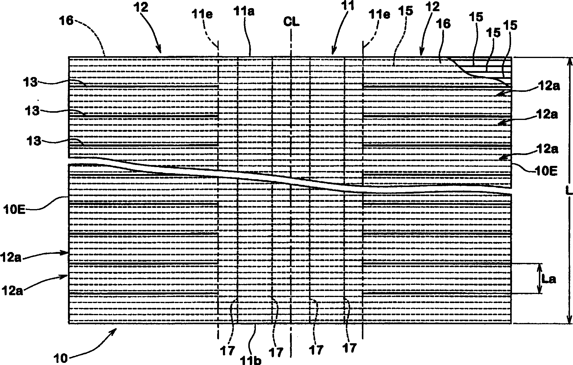
[0102] While changing the manufacturing method, based on the parameters shown in Table 1, a pneumatic tire model with a size of 175 / 65R14 for passenger cars was designed, and the uniformity level of the tire was tested. The conventional embodiment is a tire formed by a conventional manufacturing method having the expansion and deformation process of the carcass ply as shown in FIG. 24 . Comparative Example is a tire formed of a carcass ply in which belt-like strip pieces are continuously adhered to the outer side of one core as shown in FIG. 26 . In Example tire 1 of the present invention, such as Figures 14 to 16 Alternately bend the long rectangular pieces inwards as shown, then adhere the remaining long rectangular pieces to the outside. The embodiment tire 2 of the present invention comprises a carcass in which a long rectangular sheet 12a such as Figure 17 Bending inwards sequentially as shown.

[0103] Each of the above tires includes a carcass comprising a carcass ...


PUM

PropertyMeasurementUnit
lengthaaaaaaaaaa
lengthaaaaaaaaaa

Abstract

An object of the present invention is to provide a pneumatic tire with improved uniformity and a method of manufacturing the same. The pneumatic tire 1 includes a carcass and a tread, wherein the carcass is covered with a carcass ply 10 with a top rubber in an array of carcass cords radially arranged therein. The carcass ply 10 includes: a center ply portion 11 that is wound around the tread portion 2 in the tire circumferential direction and whose start end and end end in the tire circumferential direction are joined to each other; and long rectangular plies positioned on both sides of the center ply 11 Part 12. In each elongated rectangular ply portion 12, an elongated rectangular piece 12a is formed by cutting the top layer rubber into a slit 13, and each elongated rectangular ply portion 12 is bent radially inward according to the outer shape of the sidewall portion 3 in the following manner, That is, the adjacent long rectangular pieces 12a are superimposed on each other to form the side portion 6S of the carcass.

Description

technical field [0001] The present invention relates to a pneumatic tire with improved uniformity and a method of manufacturing the same. Background technique [0002] In the manufacturing process of traditional radial tires, such as Figure 24A As shown, first, a cylindrically wound carcass ply a is prepared. Each end portion of the carcass ply a is turned back around a bead core c, and sidewall rubber b is adhered to each of the two sidewall regions of the carcass ply a. Then, if Figure 24B As shown, the carcass ply a expands and deforms into a curved annular shape while reducing the gap between the bead cores c. Thus, the previously prepared endless belt d and tread rubber e can be adhered to the tread area of ​​the carcass ply a, thereby being incorporated into a green tire f. Through such expansion and deformation processes, voids are generated in a row of carcass cords in the tread portion in the carcass ply a and cord ends are reduced. This end shrinkage is not u...

Claims


Application Information

Patent Timeline
Patent Type & Authority Applications(China)
IPC IPC(8): B29D30/16B60C9/04
CPCB29D30/1607B29D30/46B29D2030/0682B60C9/0207B60C9/023B60C15/0018B60C15/04B60C15/05Y10T152/10855
Inventor 中田典克
Owner SUMITOMO RUBBER IND LTD
Why Eureka
Try Eureka