Device for detecting broken yarn through shaft frame and method for locating its address

A technology for yarn breakage detection and setting method, which is applied in the inspection of textile materials, other manufacturing equipment/tools, textiles and papermaking, etc. The effect of setting errors, saving time, and reducing costs

Inactive Publication Date: 2010-11-03
TSUDAKOMA KOGYO KK
View PDF6 Cites 0 Cited by
  • Summary
  • Abstract
  • Description
  • Claims
  • Application Information

AI Technical Summary

Problems solved by technology

First of all (1) as the 100 described in the above example, the number of slave control devices installed on the creel device is very large, and it takes time and manpower to set addresses one by one.
(2) As far as the setting operation is concerned, since the operator needs to operate the DIP switches one by one, setting errors are prone to occur
(3) Since it is necessary to provide switches for address setting to all slave control devices, the structure of the device is complicated and the price is increased

Method used


Image

  • Device for detecting broken yarn through shaft frame and method for locating its address
  • Device for detecting broken yarn through shaft frame and method for locating its address
  • Device for detecting broken yarn through shaft frame and method for locating its address

Examples


Embodiment Construction

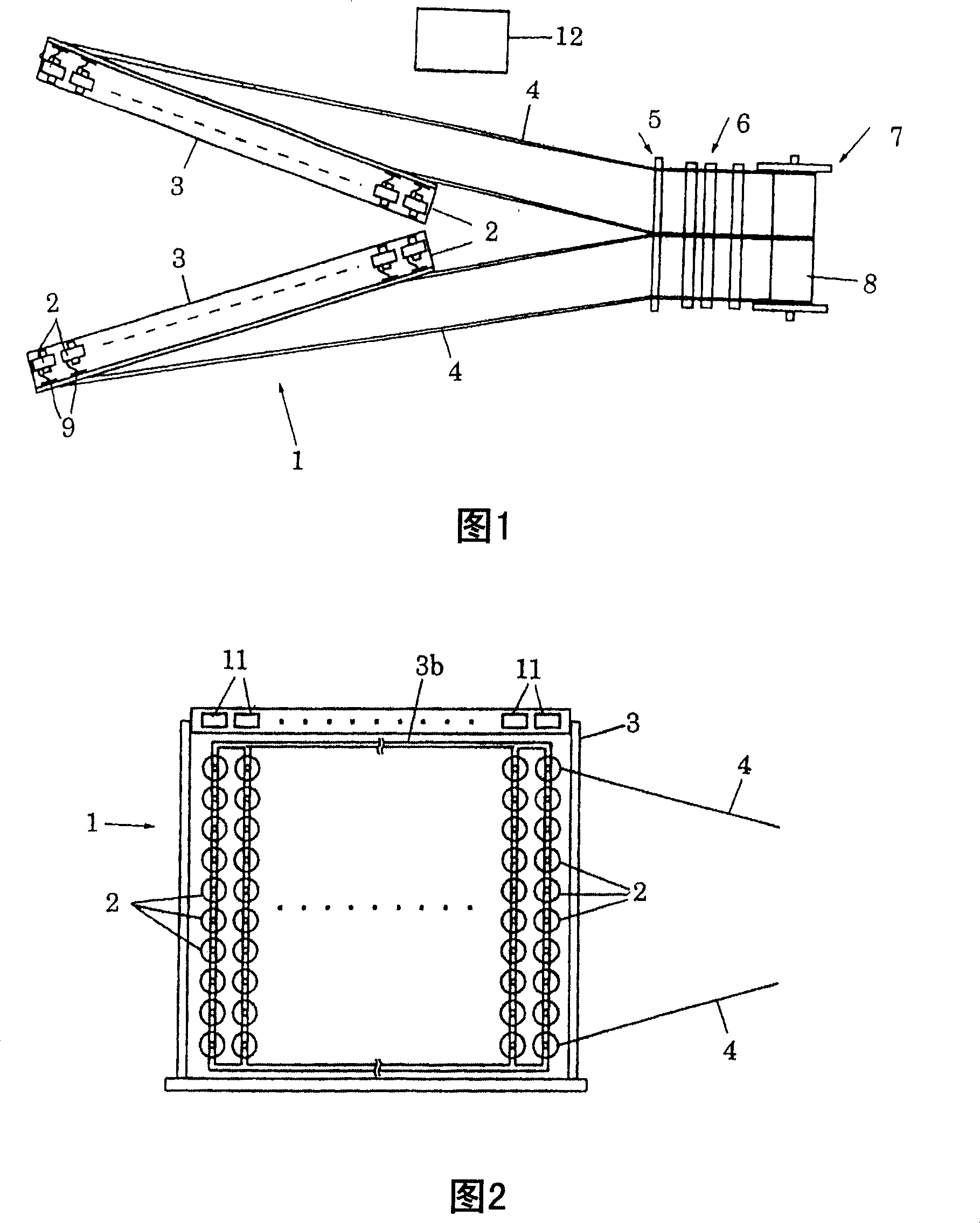
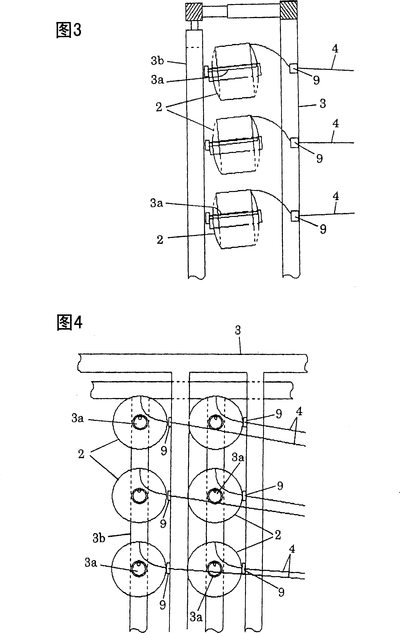
[0022] Figure 1 ~ Figure 4 The mechanical structure of the V-shaped creel device 1 is shown. exist Figure 1 ~ Figure 4 Among them, in order to support a plurality of yarn supply bodies 2, the beam creel device 1 has a V-shaped frame 3 seen in a plan view, and the yarn supply body frame 3b installed on these frames 3 has a plurality of vertical and horizontal parallel lines. Set the support member 3a. According to the illustrated example, the supporting members 3 a are arranged in ten layers in the vertical direction and arranged in N rows in the horizontal direction, and can support 10×N yarn supply bodies 2 in total. The number of yarn suppliers 2 required for warping is arranged at appropriate positions with respect to a total of 10×N supporting members 3 a. At this time, all the 10×N support members 3 a in total support the yarn supply body 2 .

[0023] A plurality of warp yarns 4 drawn from all the yarn supply bodies 2 pass through the yarn breakage sensors 9 provide...


PUM


Abstract

The invention relates to a method for locating address for plural controllers of a yarn breakage detector and the yarn breakage detector with address setting function. The yarn breakage detector is composed of a plurality of serially connected controllers corresponding to a plurality of yarn breakage sensors for each supporting member of a yarn feeding member, and a central processor for monitoring the yarn breakage in the whole creel apparatus and connected to the controllers in series. The central processor outputs a signal containing address information to the controller of the uppermost stream side. The uppermost controller recognizes / memorizes the own address based on the inputted signal, acquires the address information of the following downstream-side controller based on the inputted signal information according to a prescribed operation procedure, and outputs a signal containing the address information to the following downstream-side controller. Each controller successively sets the address to all following downstream controllers. The invention can successively automatically set address for each controller without setting address for other hardware such as DIL switch andso on.

Description

technical field [0001] The present invention relates to a method of setting addresses for a plurality of controllers of the yarn break detection device in a yarn break detection device included in a creel device, and to a yarn break detection device having an address setting function. Background technique [0002] In the preparation stage of warp beams used in looms and the like, yarns are drawn out all at once from a plurality of yarn supply bodies mounted on a creel device, and are wound around the warp beams by a winding device or the like. Among the many yarns drawn out from the creel device, even if one yarn breaks, the number of yarns wound on the warp beam will be insufficient. Therefore, in the winding process, it is necessary to Yarn detection Yarn break. In addition, when a yarn breakage occurs, the operator wishes to specify which yarn supply body the yarn breakage occurred in order to repair the yarn breakage. [0003] Therefore, a yarn breakage sensor is provi...

Claims


Application Information

Patent Timeline
Patent Type & Authority Patents(China)
IPC IPC(8): D02H13/04D06H3/00
Inventor 野村拓右
Owner TSUDAKOMA KOGYO KK
Why Eureka
Try Eureka