Cutting tool for stick material

A bar and tool technology, applied in the field of bar cutting tools, achieves the effects of reduced labor, simple structure and low cost

Inactive Publication Date: 2006-06-07
昶彰工業股ふん
View PDF1 Cites 3 Cited by
  • Summary
  • Abstract
  • Description
  • Claims
  • Application Information

AI Technical Summary

Problems solved by technology

Therefore, tool users with ordinary ...

Method used


Image

  • Cutting tool for stick material
  • Cutting tool for stick material
  • Cutting tool for stick material

Examples


Embodiment Construction

[0034] The preferred embodiments of the present invention will be described in detail below in conjunction with the accompanying drawings.

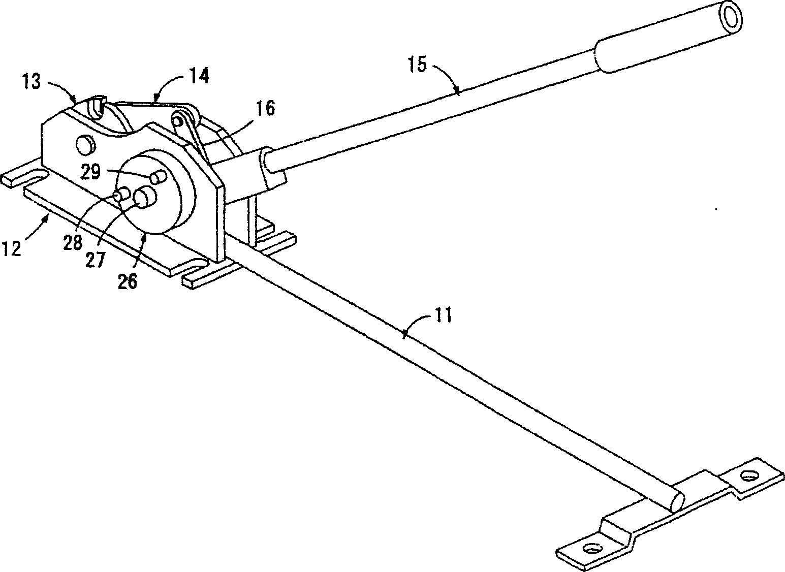
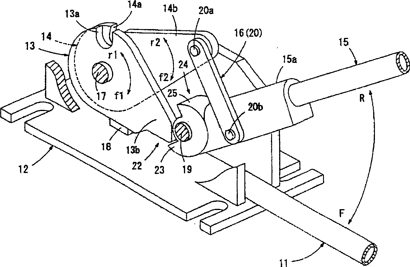
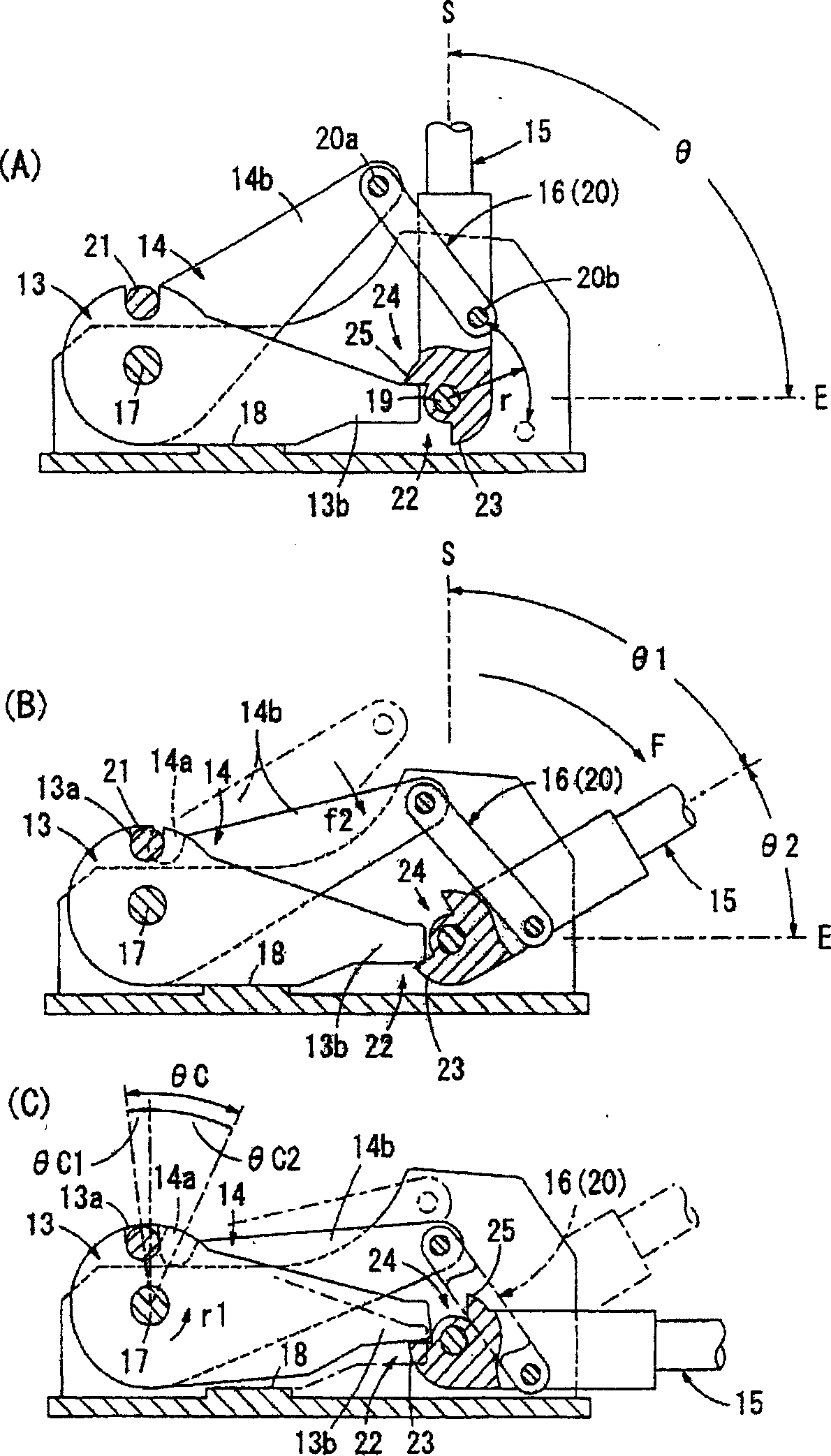
[0035] Such as figure 1 and figure 2 As shown, the cutting tool of the present invention includes a base 12 with a fixed handle 11, a first blade body 13 and a second blade body 14 mounted on the base 12, an operating lever 15 pivotally mounted on the base 12, and The link mechanism 16 of the second blade body 14 can be rotated when the operating lever is rotated.

[0036] The first blade body 13 and the second blade body 14 are supported by the support shaft 17 in a state of being overlapped with each other, and have U-shaped blades 13a, 14a respectively formed with concave grooves of the same shape on the peripheral edges. The first blade body 13 is rotatably supported on the support shaft 17, but a stop mechanism 18 is provided between the first blade body 13 and the base 12 so that it cannot rotate in the clockwise direction f1. ...


PUM


Abstract

The cutting tool for stick material includes one U-shaped edge including the first edge and the second edge superposed each other, one operating lever, and one link rod mechanism. After some rod is inserted into the U-shaped edge and the operating lever is pushed downward, the link rod mechanism will make the first edge and the second edge rotate oppositely to cut down the rod. The link rod mechanism has such structure that when the operating lever is turned in some angle, the second edge is turned in a relatively smaller angle while the first edge is fixed. In addition, there is one auxiliary driving mechanism set between the first edge and the operating lever.

Description

technical field [0001] The present invention relates to a hand tool for cutting bars such as iron bars, especially a bar cutting tool that can reduce the operating force of a lever necessary for cutting bars. Background technique [0002] Traditionally, the manual cutting tool for iron bars includes a base with a fixed handle, a fixed blade body and a movable blade body installed on the base, an operating lever pivotally mounted on the base, and when the operating lever rotates, the movable blade body rotates. the connecting rod. [0003] exist Figure 6 In the known bar cutting tool shown, the fixed blade body 1 and the movable blade body 2 are pivotally supported on the base 4 via the support shaft 3 . While the fixed blade body 1 is fixed so as not to rotate via the fixing mechanism 1b, the movable blade body 2 is rotatably supported by the support shaft 3. As shown in FIG. The fixed blade body 1 and the movable blade body 2 overlapping each other on the fulcrum have U-...

Claims


Application Information

Patent Timeline
IPC IPC(8): B23D17/08B26B17/02
Inventor 长谷川光男
Owner 昶彰工業股ふん
Why Eureka
Try Eureka