Sucking pipe connection structure of rotary compressor

A rotary compressor and connection structure technology, applied in the direction of rotary piston machinery, rotary piston pump, rotary piston/oscillating piston pump components, etc.

Inactive Publication Date: 2011-05-11
LG ELECTRONICS (TIANJIN) APPLIANCES CO LTD
View PDF8 Cites 0 Cited by
  • Summary
  • Abstract
  • Description
  • Claims
  • Application Information

AI Technical Summary

Problems solved by technology

[0017] It can be seen that the above-mentioned existing rotary compressor suction pipe connection structure obviously still has inconvenience and defects in structure and use, and needs to be improved urgently. Improve
In order to solve the problems existing in the connection structure of the suction pipe of the rotary compressor, the relevant manufacturers have tried their best to find a solution, but no suitable design has been developed for a long time, and there is no suitable structure for general products. To solve the above problems, this is obviously a problem that the relevant industry is eager to solve

Method used


Image

  • Sucking pipe connection structure of rotary compressor
  • Sucking pipe connection structure of rotary compressor
  • Sucking pipe connection structure of rotary compressor

Examples


Embodiment Construction

[0049] In order to further explain the technical means and effects of the present invention to achieve the intended purpose of the invention, the specific implementation and structure of the suction pipe connection structure of the rotary compressor proposed according to the present invention will be described below in conjunction with the accompanying drawings and preferred embodiments. , features and their effects are described in detail below.

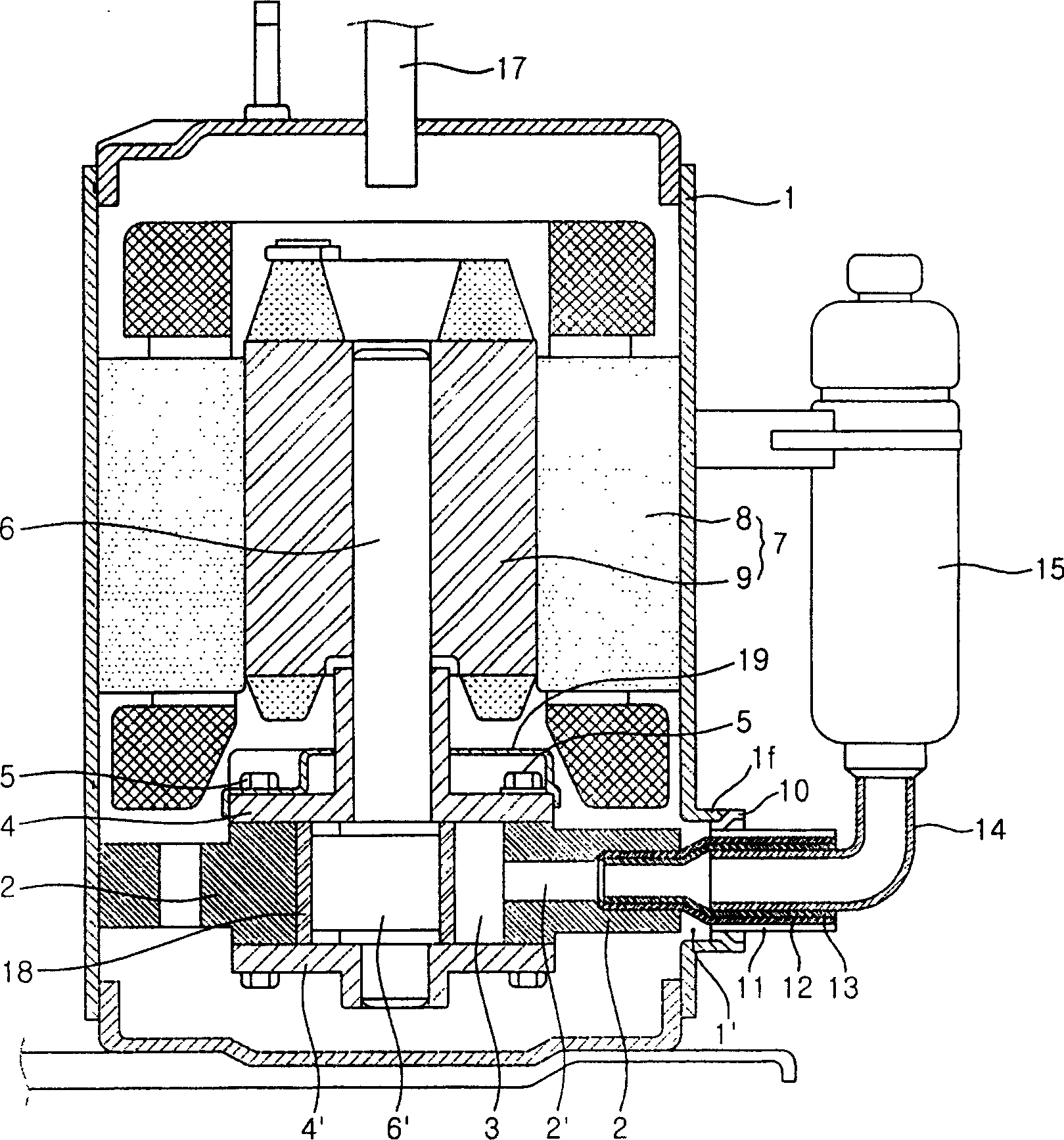
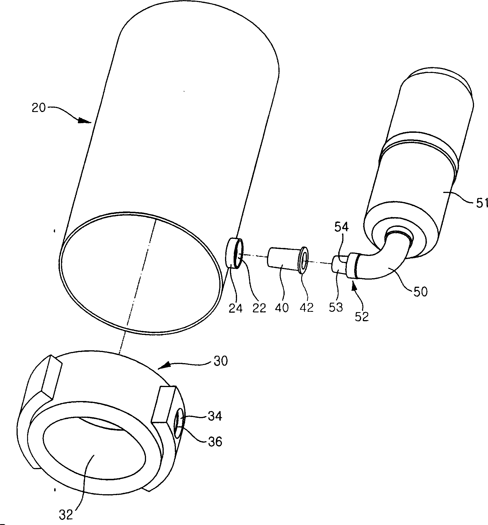
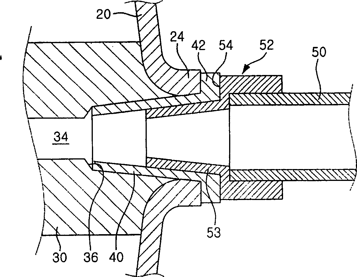
[0050] figure 2 It is an exploded oblique view of the best embodiment of the rotary compressor suction pipe connection structure of the present invention; image 3 It is a structural sectional view of an embodiment of the present invention; Figure 4 It is a perspective view when combining the embodiment of the present invention.

[0051] As shown in the figure, the casing 20 forms the appearance of a rotary compressor. The above-mentioned casing 20 has a roughly cylindrical shape and is formed in a long shape along the vertical ...


PUM


Abstract

The sucking pipe connection structure for rotary compressor includes casing, sucking pipe and adaptor. The casing has a through hole on one side and communicated to the sucking pipe and an inside closed space with cylinder with the sucking port; the sucking pipe penetrating the through hole in the casing is inserted into the sucking port of the cylinder; and the adaptor is set in the front of theconnecting pipe connected to a storage and has the insertion pipe inserted to transmit the work fluid from the storage to the sucking pipe. The casing with flange, the sucking pipe with flange and the adaptor with flange are connected through welding.

Description

technical field [0001] The present invention relates to a rotary compressor, in particular to a suction tube connecting structure of a rotary compressor that transmits a working fluid to the interior by penetrating through a shell that forms the appearance structure of the rotary compressor compressor). Background technique [0002] figure 1 It is a cross-sectional view of the internal structure of a common rotary compressor. As shown in the drawing, the casing 1 forming a closed space inside has a compressor component part on the lower side thereof. That is, the inner lower side of the above-mentioned casing 1 is fixed with the cylinder 2, and the inside of the above-mentioned cylinder 2 is provided with a compression chamber 3, and the upper and lower parts of the above-mentioned compression chamber 3 are covered by upper and lower bearings 4, 4'. The above-mentioned upper and lower bearings 4, 4' are connected to the upper and lower parts of the above-mentioned cylinde...

Claims


Application Information

Patent Timeline
Patent Type & Authority Patents(China)
IPC IPC(8): F04C29/12F04C18/00
Inventor 姜完奉
Owner LG ELECTRONICS (TIANJIN) APPLIANCES CO LTD
Why Eureka
Try Eureka