Tault component transformer longitudinal error protecting method with maximum side zero sequence ratio brake
A fault component, ratio braking technology, applied in emergency protection circuit devices, electrical components, etc., can solve problems such as the inability to completely eliminate zero-sequence current
- Summary
- Abstract
- Description
- Claims
- Application Information
AI Technical Summary
Problems solved by technology
Method used
Image
Examples
Embodiment 1
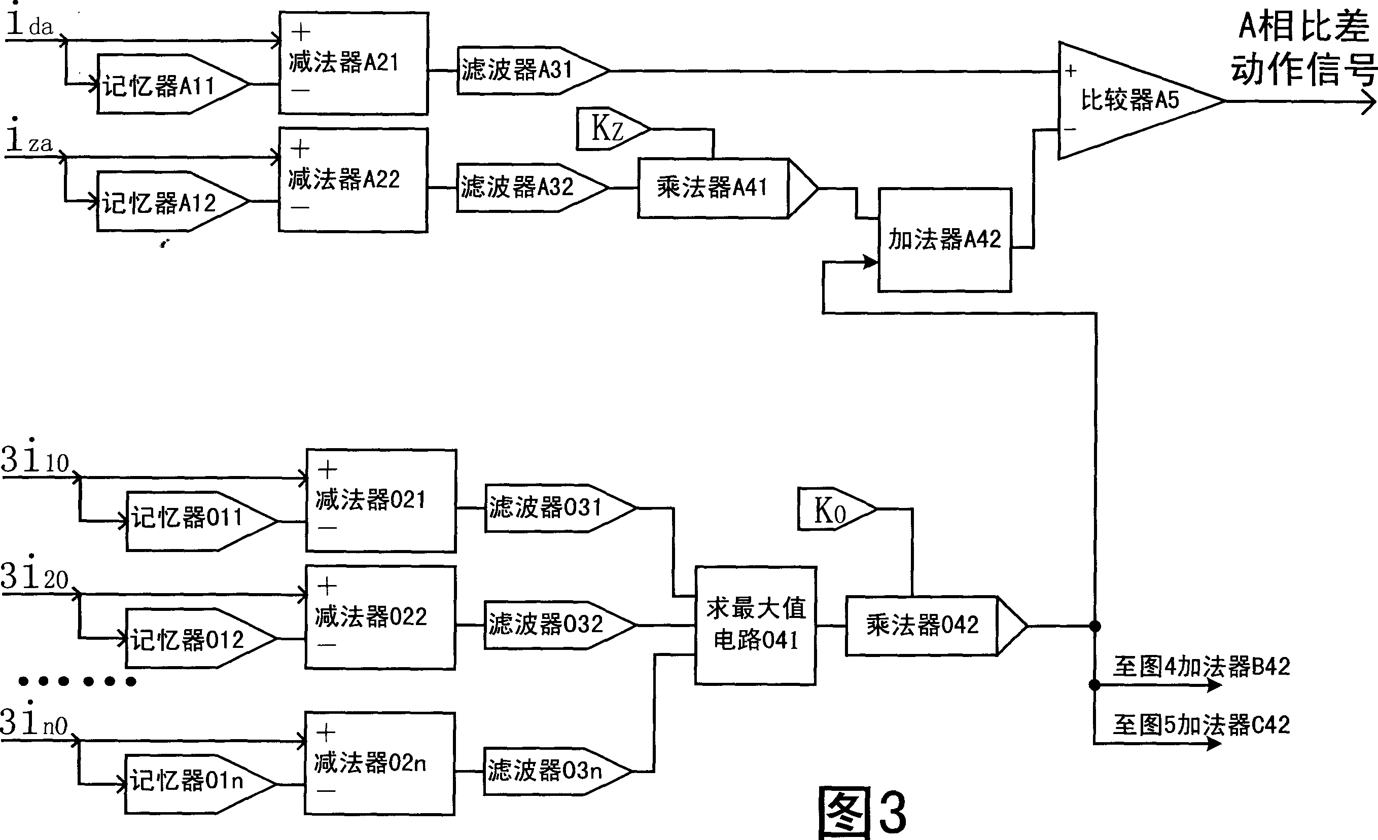
[0017] A longitudinal differential protection method for fault component transformers with maximum side zero-sequence ratio braking, which can be achieved through Fig. 3- Figure 5 The circuit block diagram of a fault component transformer differential protection element with maximum side zero-sequence ratio braking is realized. The element consists of a memory A 11 , B 11 、C 11 、A 12 , B 12 、C 12 , 011, 012, 013, subtractor A 21 , B 21 、C 21 、A 22 , B 22 、C 22 , 021, 022, 023, filter A 31 , B 31 、C 31 、A 32 , B 32 、C 32 , 031, 032, 033, maximum value seeking circuit 041, multiplier A 41 , B 41 、C 41 , 042, adder A 42 , B 42 、C 42 and comparator A 5 , B 5 、C 5 constitute. where memory A 11 , B 11 、C 11 input and the subtractor A 21 , B 21 、C 21 The positive input ends of the transformer Y are respectively input 0 The instantaneous value signal of the three-phase differential current on the side i da i db i dc , memory A 11 , B 11 、C 11 Th...
PUM
 Abstract
Description
Claims
Application Information
 - R&D
- Intellectual Property
- Life Sciences
- Materials
- Tech Scout
- Unparalleled Data Quality
- Higher Quality Content
- 60% Fewer Hallucinations
Browse by: Latest US Patents, China's latest patents, Technical Efficacy Thesaurus, Application Domain, Technology Topic, Popular Technical Reports.
© 2025 PatSnap. All rights reserved.Legal|Privacy policy|Modern Slavery Act Transparency Statement|Sitemap|About US| Contact US: help@patsnap.com


