
Fault component transformer longitudinal error protecting element with multiple side zero sequence ratio brake

A technology of ratio brake and fault component, which is applied in the direction of electrical components, emergency protection circuit devices, etc., to achieve the effect of avoiding inconsistent errors

Inactive Publication Date: 2006-06-07
ZHEJIANG UNIV
View PDF0 Cites 4 Cited by
  • Summary
  • Abstract
  • Description
  • Claims
  • Application Information

AI Technical Summary

Problems solved by technology

Visible, by Y 0 The unbalanced current caused by side zero-sequence fault current is ignored in the traditional ratio differential protection

Method used


Image

  • Fault component transformer longitudinal error protecting element with multiple side zero sequence ratio brake
  • Fault component transformer longitudinal error protecting element with multiple side zero sequence ratio brake
  • Fault component transformer longitudinal error protecting element with multiple side zero sequence ratio brake

Examples


Embodiment 1

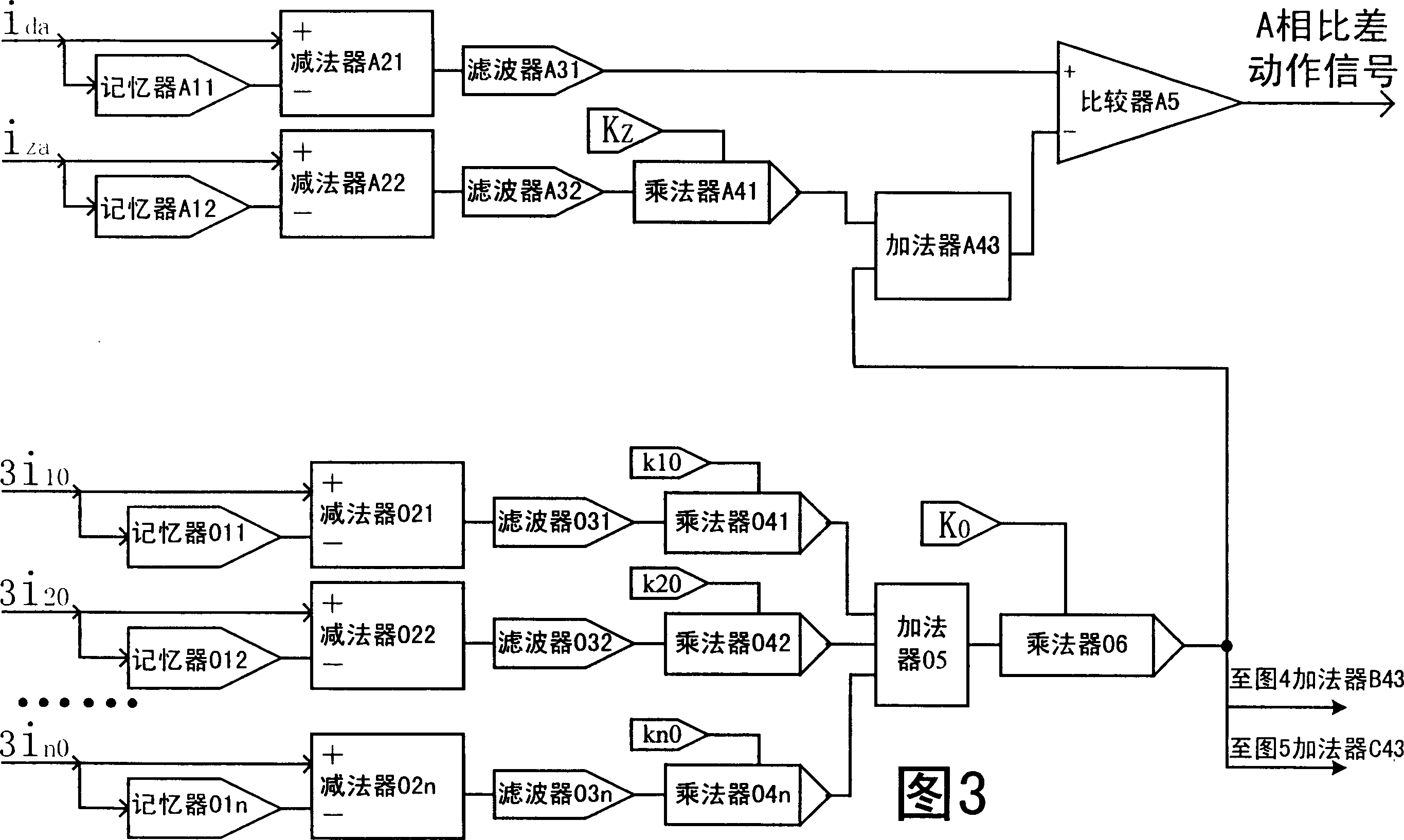
[0015] A fault component transformer longitudinal differential protection element with multi-side zero-sequence ratio braking, which can be used as shown in Figure 3- Figure 5 The circuit block diagram of a fault component transformer differential protection element with multi-side zero-sequence ratio braking is realized. Among them, the preset weight k 10 、k 20 、…k n0 , the value is 0.5, n=3 is the number of neutral grounding sides (or branches) of the transformer, and the zero-sequence braking coefficient K 0 =0.2, the ratio braking coefficient K in the existing ratio differential protection Z , whose value is 0z 0 The misoperation of the transformer differential protection caused by the ground fault outside the side area can also prevent the misoperation of the transformer differential protection caused by the differential unbalanced current caused by the zero-sequence current under other non-internal fault conditions, and does not affect the fault situation in the area...


PUM


Abstract

This invention discloses a longitudinal deviation protection element of a fault component transformer with multiple side zero sequence rate brakes, in which, the brake current fault components of three phases representing the through current in the present transformer differential protection is weighted with the weighted values of zero sequence currents of neutral point earth sides to get the fault components of the brake currents with zero sequence currents of the three phases to be used to make up of rate differential elements of related phases with the differential current components, when that of the differential current is greater than that of the brake current containing zero sequence current, a rate differential action signal of related phase is output.

Description

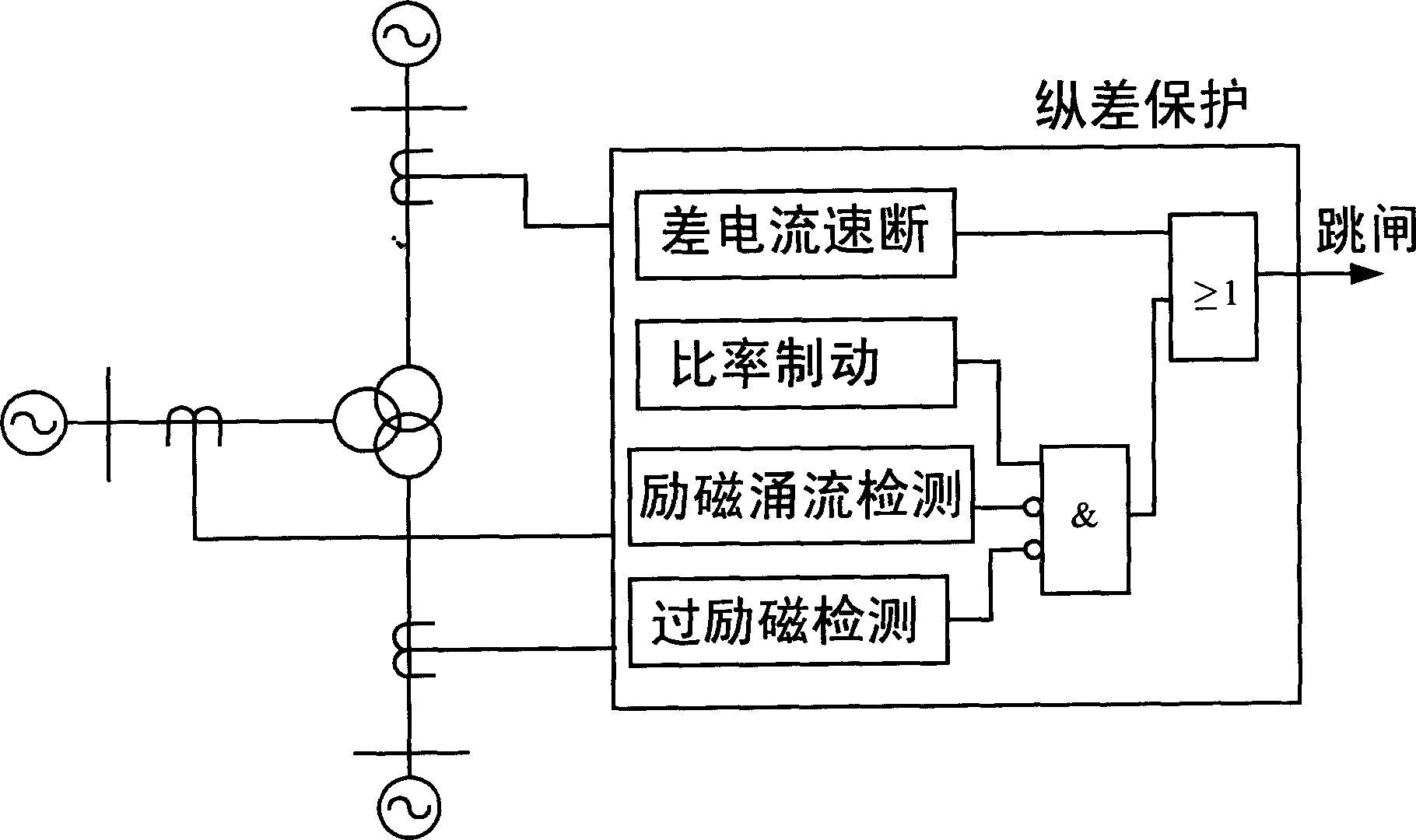
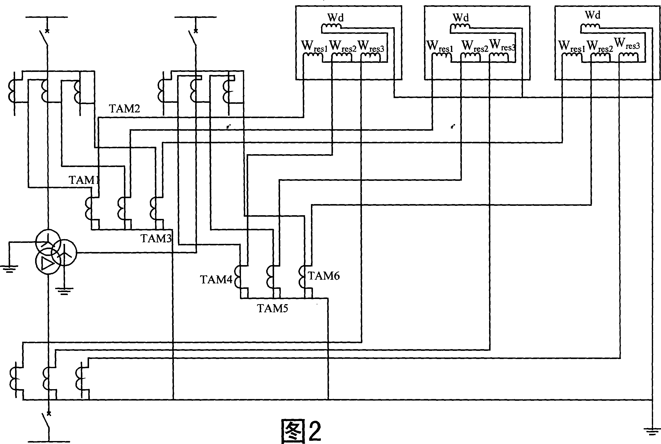
technical field [0001] The invention relates to a power system relay protection element, in particular to a fault component transformer longitudinal differential protection element with multi-side zero-sequence ratio braking. Background technique [0002] The current longitudinal differential protection of power transformers consists of components such as differential quick-break, ratio differential, excitation inrush current detection, and over-excitation detection. According to DL / T 684-1999 "Large Generator Transformer Relay Protection Setting Calculation Guidelines", the block diagram of transformer differential protection is shown in figure 1 As shown, the wiring example of longitudinal differential protection principle is shown in Figure 2. Usually using a current transformer for Y 0 Y / Δ transformation is performed on the three-phase current on the side to eliminate the influence of zero-sequence current. Obviously, after the transformation, each current does not co...

Claims


Application Information

Patent Timeline
Patent Type & Authority Applications(China)
IPC IPC(8): H02H7/045
Inventor 徐习东
Owner ZHEJIANG UNIV
Learn More