Modular rear projection display and combined device used thereof

A technology for display devices and combined devices, which is applied in the direction of using projection device image reproducers, projectors with built-in screens/external screens, and projection devices, which can solve the problem of costly mold opening and development costs, and rear projection display Problems such as increased device cost and difficulty in product assembly have achieved the effects of saving development costs, reducing inventory opportunities, and reducing costs

Inactive Publication Date: 2006-06-07
CORETRONIC
View PDF0 Cites 0 Cited by
  • Summary
  • Abstract
  • Description
  • Claims
  • Application Information

AI Technical Summary

Problems solved by technology

[0004] The front frame 402, the rear screen shell 404, and the base 406 of the prior art are all in contact with the screen and are related to the size of the screen. Such a combination method has a disadvantage. When it is necessary to produce back screens with different screen sizes The projection display device 2, such as 52 o'clock, 56 o'clock, 60 o'clock..., must be matched with the front frame 402, rear screen shell 404, and base 406 of different sizes, and the manufacturer needs to spend more on mold opening and development. cost
[0005] In addition, the optical machine 6 is directly installed inside the combination device 4. In order to prevent the high heat of the optical machine 6 from being transferred upwards to structures such as the screen 8 that cannot withstand high temperatures, a heat shield needs to be installed inside the screen housing 404. 10. In this way, many difficulties will occur in product assembly
[0006] In addition, the position where the electronic device is placed in the rear projection display device must meet the requirements of a fire protection level in safety regulations. However, in the conventional display device, electronic devices such as the optical engine 6 and the power supply are placed on the rear screen case 404 and the base. In the space formed by 406, the materials of the entire rear screen shell 404 and the base 406 must be made of expensive fireproof materials in order to reach the fireproof level of safety regulations, so the cost of the rear projection display device will increase

Method used


Image

  • Modular rear projection display and combined device used thereof
  • Modular rear projection display and combined device used thereof
  • Modular rear projection display and combined device used thereof

Examples


Embodiment Construction

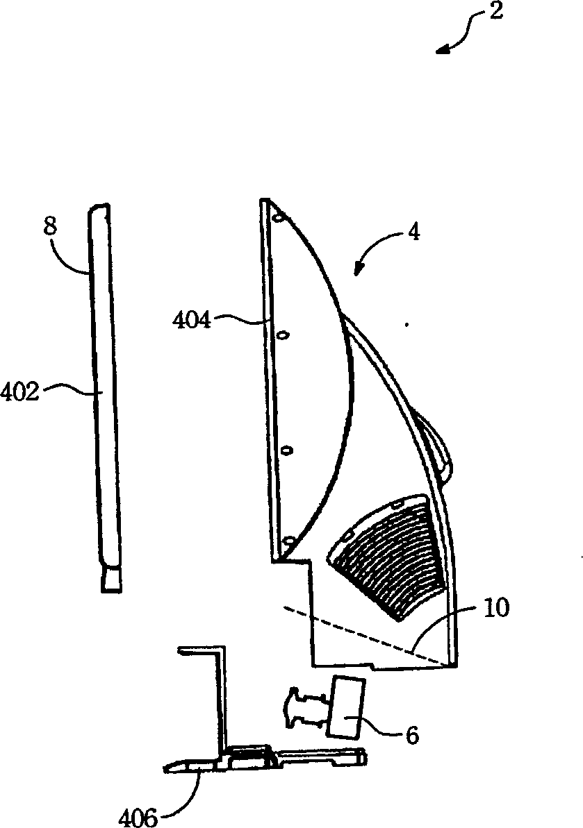
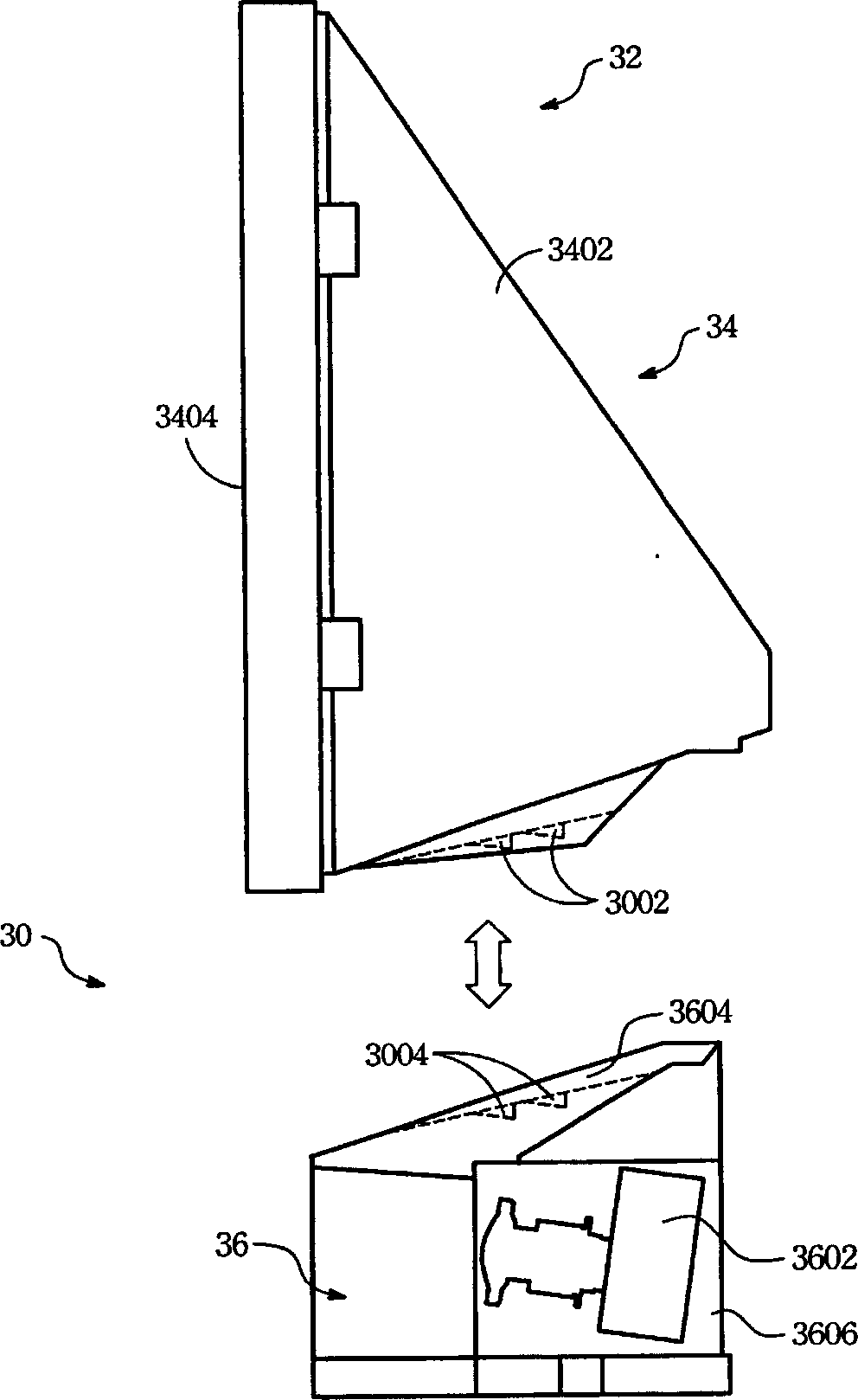
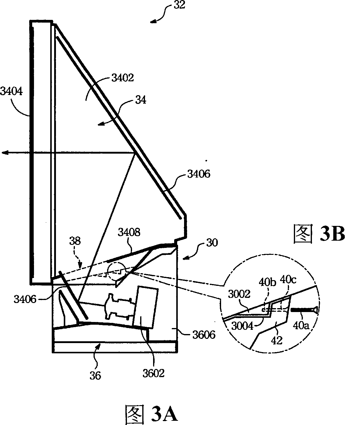
[0048] see figure 2 and Figures 3A, 3B, figure 2It is an exploded schematic view of the combination device 30 of the present invention. FIG. 3A is a combined schematic view of the combination device 30 of the present invention. The present invention relates to a modularized rear projection display device 32 and a combination device 30 for the rear projection display device 32, using the combination device 30 to combine the modularized screen module 34 in the rear projection display device 32 And the optomechanical module 36. The optical engine module 36 includes an optical engine housing 3606 and an optical engine 3602 disposed in the optical engine housing, and the screen module 34 includes a screen housing 3402 , a screen 3404 , and a reflector 3406 .

[0049] The screen 3404 is arranged on the front of the screen housing 3402 . The reflector 3406 is arranged inside the screen housing 3402, and is used to reflect the image light from the bottom light engine 3602 and pr...


PUM


Abstract

A combination structure is used in a rear projection display device, for combining a screen module and an optical engine module in the rear projection display device. The combination structure includes a first positioning structure and a second positioning structure, the first positioning structure being disposed under the screen module, the second positioning structure being corresponding to the first positioning structure and disposed above the optical engine module. Wherein, the first positioning structure and the second positioning structure are matched up to be connected together, for the screen module to be directly connected with the optical engine module.

Description

【Technical field】 [0001] The present invention relates to a rear projection display device, in particular to a modular rear projection display device and a combination device for the rear projection display device. 【Background technique】 [0002] Among several types of flat panel displays gradually becoming mainstream, rear projection display devices have the advantages of power saving, large display area, and low price, and are quite popular in the consumer market. [0003] see figure 1 , figure 1 is a schematic diagram of a combination device 4 of a rear projection display device in the prior art. In addition to the optical engine 6 inside the conventional rear projection display device 2 , the housing combination device 4 mainly includes a front frame 402 , a rear screen housing 404 , and a base 406 . [0004] The front frame 402, the rear screen shell 404, and the base 406 of the prior art are all in contact with the screen and are related to the size of the screen. S...

Claims


Application Information

Patent Timeline
IPC IPC(8): H04N5/74H04N9/31
CPCH04N9/3141G03B21/10G03B21/145
Inventor 曾湧泉曹建明
Owner CORETRONIC
Why Eureka
Try Eureka