Position locking device for breaker

A technology for locking devices and circuit breakers, which is applied to switchgear, horizontal pull-isolated switchgear, pull-out switchgear, etc., can solve the problems of increased manufacturing costs, achieve the effect of reducing precision and avoiding destructive damage

Active Publication Date: 2006-06-14
SEARI ELECTRIC TECH
View PDF1 Cites 4 Cited by
  • Summary
  • Abstract
  • Description
  • Claims
  • Application Information

AI Technical Summary

Problems solved by technology

All of these make the accuracy and strength requirements of each transmissi

Method used


Image

  • Position locking device for breaker
  • Position locking device for breaker
  • Position locking device for breaker

Examples


Embodiment Construction

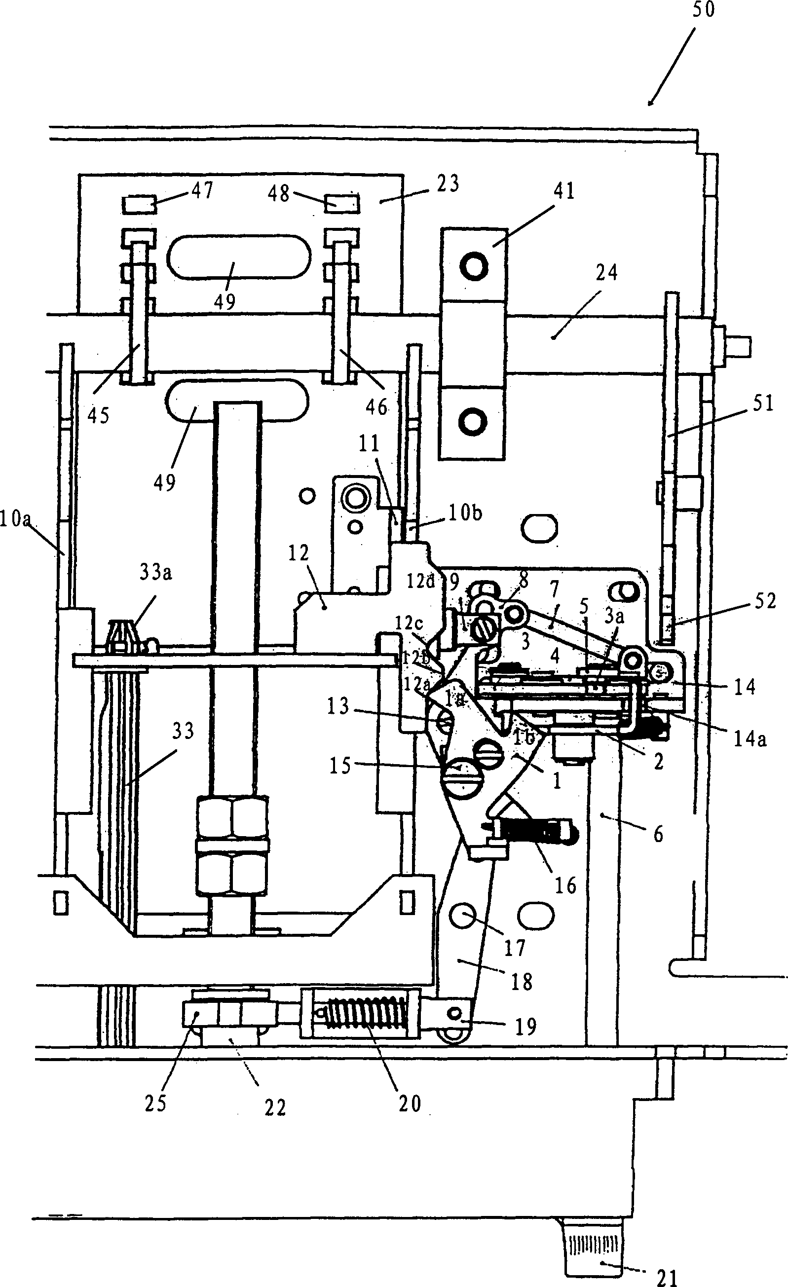
[0033] refer to figure 1 , figure 1 It is a plan view showing the general structure of the position locking device of a circuit breaker according to a preferred embodiment of the present invention. What is shown in the figure is a part of the drawer seat 50 as the position locking device in the drawer type circuit breaker, which is located under the circuit breaker body (not shown). The circuit breaker body can be arranged on the left and right sides of the drawer seat 50 ( figure 1 Only the right side is shown in the figure) Between the upper guide rail 51 and the lower guide rail 52 as the second constraining guide rail, the translation of the circuit breaker body in the depth direction of the circuit breaker is realized by sliding the sliding end between the upper and lower guide rails 51 and 52 (see also Image 6 ). To realize this kind of translation of the circuit breaker body, the main rotating shaft 24 as the rotation pivot that fixes the upper and lower guide rail...


PUM


Abstract

This invention provides a location locking device of a breaker including: a dismountable operation piece, a drive restrict unit combining with the operation piece uniformly driving the breaker body to translate on the throat direction, a position display unit displaying the moving position of the breaker, a trigger unit for triggering with the position display unit, a position locking unit for locking the position of the drive restrict unit along the trigger action of the trigger unit and an unblock operation unit unblocking the position locking

Description

technical field [0001] The present invention relates to a position locking device of a circuit breaker, in particular to a position locking device used in a drawer type circuit breaker for position locking / unlocking after each circuit breaker body is in the separation, test and connection positions. Background technique [0002] Chinese Invention Patent Application Publication No. CN 1223448A discloses a position locking device for a drawer type circuit breaker. The circuit breaker drives a transmission system to make the circuit breaker The main body can be switched between the three positions of disengagement, test and connection in the depth direction. When the circuit breaker body is at the outermost separation position in the depth direction, the main circuit included in the circuit breaker body and the control circuit for controlling are both in a state of being separated from the application main circuit of the circuit breaker. When the circuit breaker body is in the...

Claims


Application Information

Patent Timeline
IPC IPC(8): H02B11/12H02B11/133H02B11/173
Inventor 陈培国周密万里浩谈行谈建平
Owner SEARI ELECTRIC TECH
Why Eureka
Try Eureka