

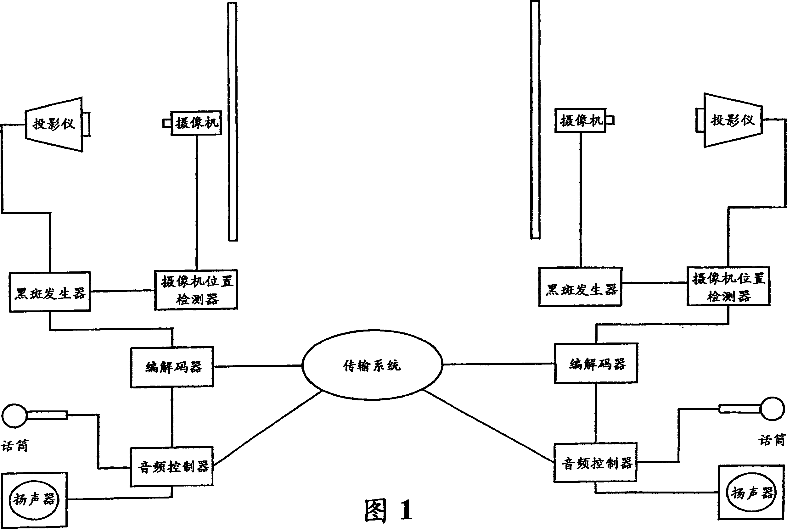
An arrangement and method for permitting eye contact between participants in a videoconference
A technology for video conferencing and video, applied in the field of video capture and display systems, can solve problems such as the inability to capture user images and the unnatural adjustment of the user's head position.
- Summary
- Abstract
- Description
- Claims
- Application Information
AI Technical Summary
Problems solved by technology
Method used
Image

Examples
Embodiment Construction
[0016] Best Mode for Carrying Out the Invention
[0017] The present invention will be discussed below by illustrating preferred embodiments and referring to the accompanying drawings. However, those skilled in the art will realize other applications and modifications within the scope of the invention as defined by the appended claims.
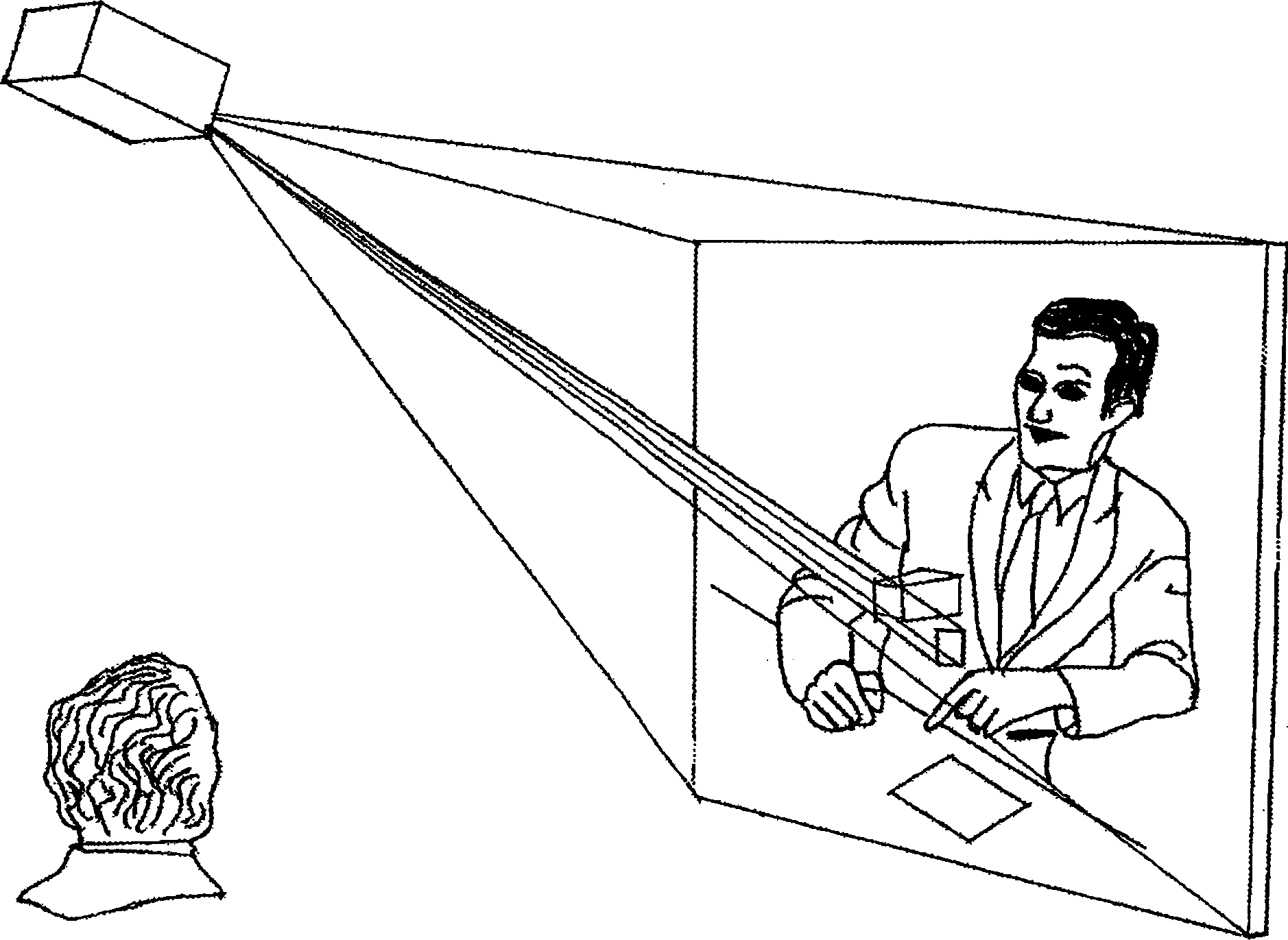
[0018] The present invention will use standard front projection equipment as a generator to display images on a videoconference. That is to say, the present invention can use the original display equipment installed in conference rooms, classrooms, etc. as the display device at the end of the video conference, and at the same time provide visual contact between participants in different conference venues. refer to figure 2 , which shows an endpoint device according to an exemplary embodiment of the present invention. The user is watching the image of the remote site projected onto the linen by the projector receiving the picture from the en...
PUM
 Abstract
Description
Claims
Application Information