
Eureka
For R&D, Eureka makes reading and utilizing patents & technical documents easy.
Eureka AIR
Designed for self-driven R&D workflows. Generate viable solutions, solve complex R&D challenges, empower your innovation with AI.

Eureka Materials
Designed for material experts only. Revolutionize your material R&D, from search, analyze, to developing new materials.

TechResearch
Generate reliable direction feasibility study reports for your R&D in just a few steps.

TechSeek
Discover and master advanced knowledge NOW. Basics, ideas, possibilities, all at once.

TechMind
As an expert in R&D Theories, TechMind can generates customized viable solutions instantly.

TechRisk
Analyze your overall solution with one click, know your potential R&D risks in advance.

TechMonitor
Get weekly tech updates, stay abreast of the latest tech innovations and key insights.
Warehouse device
A warehouse and clamping piece technology, applied in the field of warehouse management automation equipment, can solve the problems of poor practicability, low shipping efficiency, high labor intensity, etc. Effect
- Summary
- Abstract
- Description
- Claims
- Application Information
AI Technical Summary
Problems solved by technology
Method used
Image

Examples
Embodiment 1
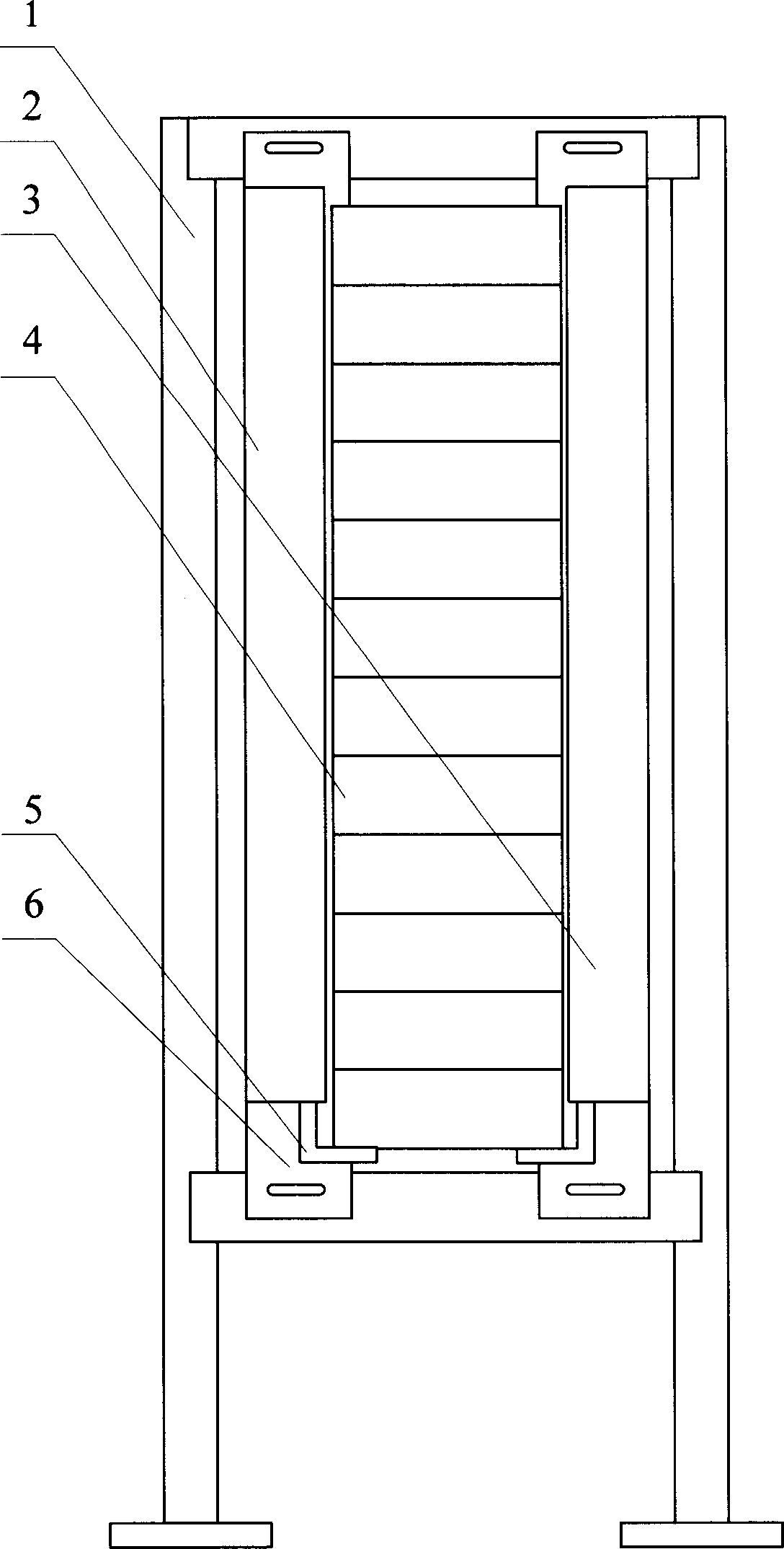
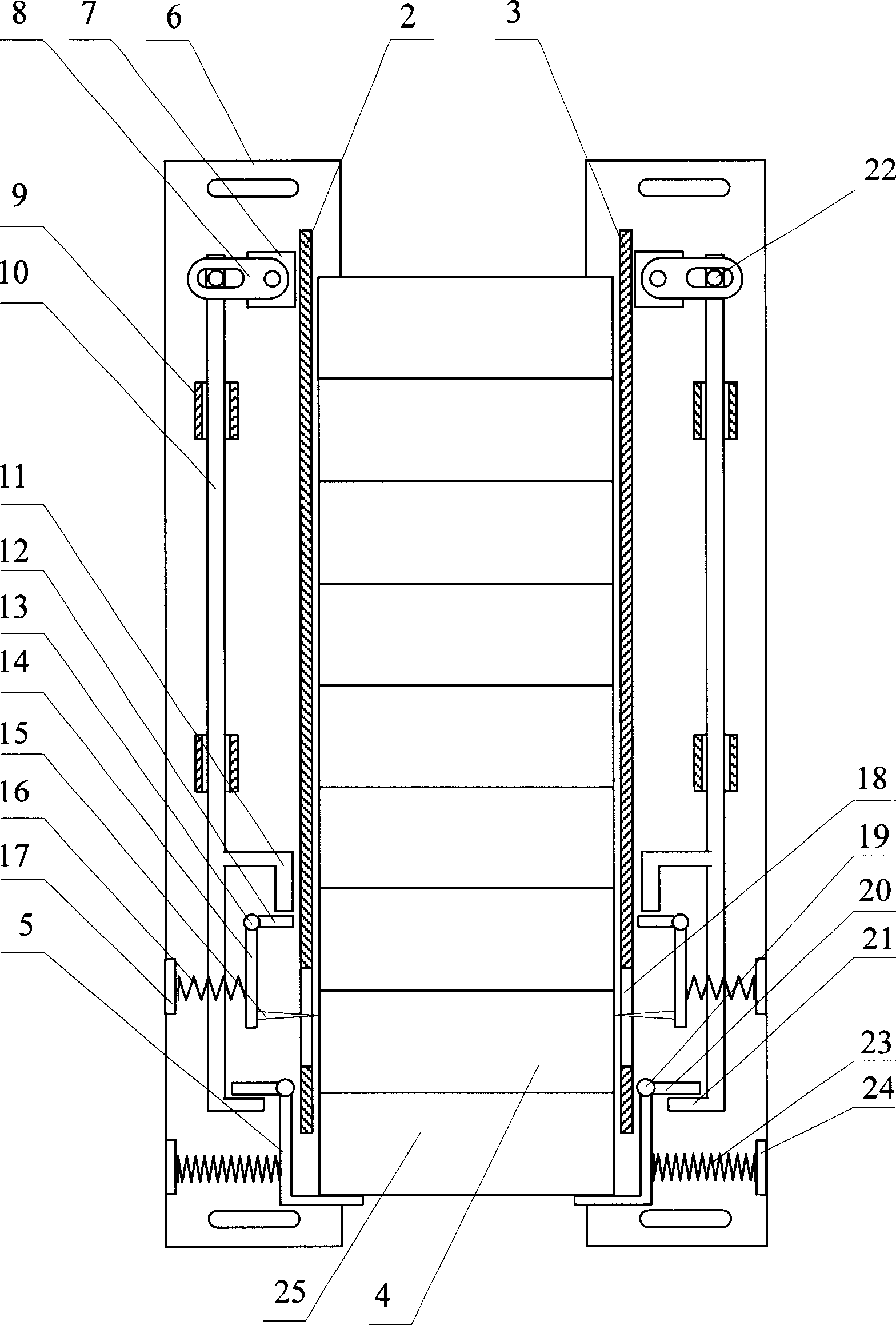
[0033] Such as figure 1 , 2 As shown in and 3, this embodiment is the situation that "the two partitions are provided with a stop mechanism and a clamping mechanism" listed in the summary of the invention. The specific structure includes: partitions 2 and 3 arranged on the bracket 1 The strip-shaped connecting plate 6 is a component of the partitions 2 and 3, and is the base plate on which the partitions 2 and 3 are installed on the bracket 1. It is the same in each embodiment described later. The long holes at the upper and lower ends of the connecting plate 6 are partitions. Plates 2, 3 are connected to the screw holes of the upper and lower crosspieces of the support 1; the partitions 2, 3 are all provided with the same catch mechanism and clamping mechanism, and the catch mechanism is composed of the catch piece 5, the hinge support shaft 19 of the catch piece, The stop piece crank 20 and back-moving spring 23 constitute, and the stop piece 5, the stop piece hinge support...
Embodiment 2
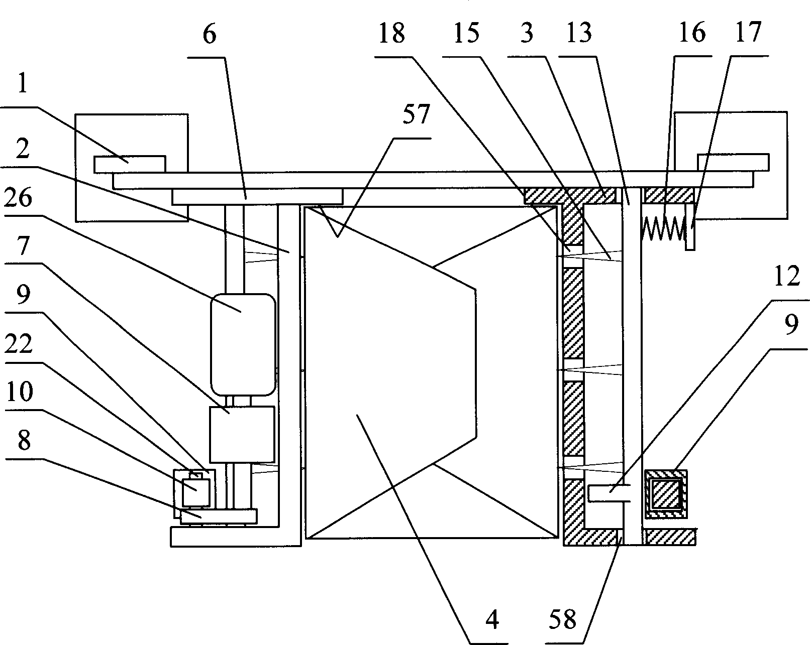
[0039] Such as Figure 9 , 10 As shown in 11 and 11, this embodiment is the setting condition of "one partition has a stop mechanism and a clamping mechanism and the other partition is a light board" listed in the summary of the invention. The specific structure includes: Partition 2 and 3, the shape of partition 2 is the same as embodiment 1, partition 3 is a light plate, and connecting plate 6 is unchanged; The mechanism is composed of a worm 33, a worm shaft 32, gears 30, 31 and an electric motor 26 as a power device. The stop piece 5, the hinge support shaft 19 of the stop piece and the worm wheel 34 are connected as one, and are horizontally hinged on the partition plate 2. The mouth piece 5 cantilever out, the worm shaft 32 is fixed at both ends of the worm shaft 33 and the middle part is fixed with the gear 31 and hinged to the partition 2, the gear 30 is fixed at the shaft end of the motor 26, the worm 33 meshes with the worm wheel 34, and the gear 30 meshes with the ...
Embodiment 3
[0044] Such as Figure 12 As shown, this embodiment is the setting situation of "one partition has a stop mechanism and a clamping mechanism and the other partition has only a stop mechanism" listed in the summary of the invention. The specific structure includes: setting on the bracket 1 The partitions 2 and 3 have the same shape as in Example 1, but the surface of the partition 2 in contact with the goods 4 has a rubber covering layer 40, and the partition 3 is provided with a pressure hole 37; the stop mechanism is composed of a stop part 5, a stop Sliding seat 36, return spring 23 constitute, stop piece slide seat 36 is fixed on dividing plate 2,3, and stop piece 5 can slide left and right in it, and return spring 23 two ends are connected with stop piece 5 and stop piece respectively. The sliding seat 36 offsets each other; the clamping mechanism is composed of the clamping piece 14, the hinged support shaft 13 of the clamping piece, the rubber column 38 and the pressuriz...
PUM
 Abstract
Description
Claims
Application Information
 - R&D Engineer
- R&D Manager
- IP Professional
- Industry Leading Data Capabilities
- Powerful AI technology
- Patent DNA Extraction
Browse by: Latest US Patents, China's latest patents, Technical Efficacy Thesaurus, Application Domain, Technology Topic, Popular Technical Reports.
© 2024 PatSnap. All rights reserved.Legal|Privacy policy|Modern Slavery Act Transparency Statement|Sitemap|About US| Contact US: help@patsnap.com