Method and apparatus for removing viscous ash deposit in boiler

A kind of ash accumulation and boiler technology, which is applied in the direction of combustion method, removal of solid residue, and treatment of combustion products, etc. It can solve the problems of poor removal effect, high cost of ash removal, easy adhesion of steel balls and viscous ash accumulation, etc., to achieve The method is simple and flexible, the cost of ash removal is increased, and the cost is low

Inactive Publication Date: 2006-06-21
INST OF ENGINEERING THERMOPHYSICS - CHINESE ACAD OF SCI
View PDF1 Cites 24 Cited by
  • Summary
  • Abstract
  • Description
  • Claims
  • Application Information

AI Technical Summary

Problems solved by technology

[0005] The purpose of the present invention is to overcome the disadvantages of the prior art, such as poor cleaning effect, easy adhesion of steel balls with viscous ash, and high ash removal cost in the prior art, so as to provide an efficient and simple boiler viscous cleaning method. Method of accumulating dust

Method used


Image

  • Method and apparatus for removing viscous ash deposit in boiler

Examples


Embodiment 1

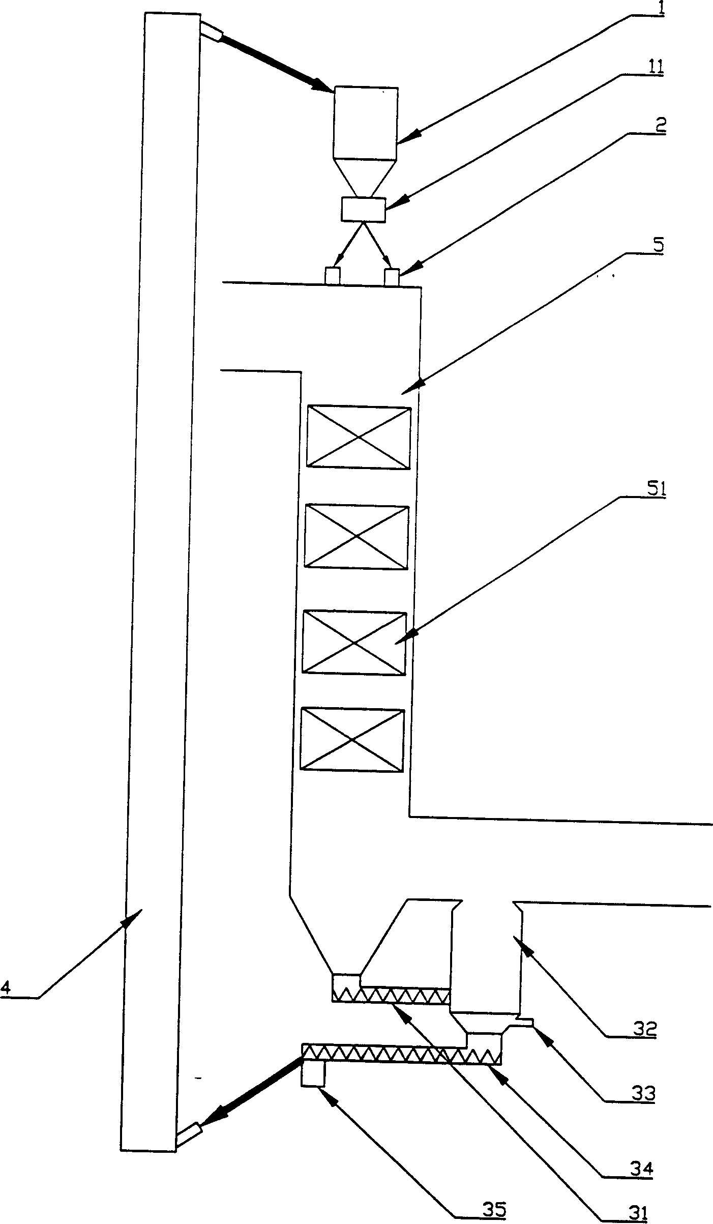
[0025] In a circulating fluidized bed boiler, there are eight particle inlets 2 on the top of the tail flue 5, all of which are connected to the hopper 1 through the particle addition control device 11; after the particles are added to the tail flue 5 from the particle inlet 2, they Flush the tube bundle 51 to take away the ash accumulated on the tube bundle 51; the particles and ash are deposited at the bottom of the tail flue 5, and are fed into the fluidization chamber 32 through the feeding screw feeder 31, and the air flows from the fluidization air inlet 33 at the bottom of the fluidization chamber 32 Enter the fluidization chamber 32 to fluidize the particles and the accumulated ash washed down. The ash is lighter and smaller, and enters the rear section of the tail flue from the top of the fluidization chamber together with the fluidization air, and the particles are discharged from the bottom of the fluidization chamber. The screw feeder 34 feeds the particle return de...

Embodiment 2

[0027] For a biomass-fired boiler, there are four particle inlets on the top of the tail flue 5, all of which are connected to the hopper 1 through the particle addition control device 11; The tube bundle 51 takes away the ash accumulation on the tube bundle 51; the particles and ash are deposited at the bottom of the flue, and are sent to the fluidization chamber 32 through the feeding screw feeder 31. Due to the high tar content in the ash produced by biomass incineration, the particles and ash The ash is bonded and discharged through the bypass outlet 35 at the outlet of the discharge screw feeder 34, and is not sent to the particle sorting device and the particle return device 4; new particles need to be added to the hopper 1. Particles use river sand with a particle size of 0.5-4mm. The ash removal system operates intermittently.

Embodiment 3

[0029] A garbage incinerator, the top of the tube-type waste heat boiler has two particle inlets 2, both of which are connected to the hopper 1 through the particle dosage control device 11; after the particles are added to the tail flue from the particle inlet 2, the tube bundle is washed with the flue gas 51, take away the ash accumulation on the tube bundle 51; the particles and ash are deposited at the bottom of the flue, and are sent into the fluidization chamber 32 through the feeding screw feeder 31, and the air enters the fluidization chamber 32 from the fluidization air inlet 33 at the bottom of the fluidization chamber , to fluidize the particles and the accumulated ash washed down. The ash is lighter and smaller, and enters the rear section of the tail flue from the top of the fluidization chamber together with the fluidization air, and the particles are discharged from the bottom of the fluidization chamber and passed through the discharge screw feeder 34 The partic...


PUM


Abstract

This invention relates to one method and device to remove adhesive dust in oven, wherein the method comprises the following steps: Joining the particles from oven tail smoke channel or remaining oven top along with smoke to tube beam to take off its surface dust; depositing the dust and particles one the smoke channel bottom to enter flow bed filtering device; the air outside smoke channel entering flow chamber to flow the particle and dust from flow chamber top to smoke channel back section; the particle are sent to the feed back device through the flow chamber bottom discharge screw through gas force transmission system or lift machine to send to materials bin; if the particle and dust are severely stuck, then from bin screw to re-fill particle from the side exhaust system by the bin.

Description

technical field [0001] The invention relates to a boiler soot blowing method and a device thereof, in particular to a method and a device for removing viscous ash deposits in boiler tail flue by using particles. Background technique [0002] Usually, there will be dust accumulation on the rear heating surface of the boiler or on the tube bundle of the tube heat recovery boiler. These ash deposits will affect the heat exchange effect of the boiler and reduce the efficiency of the boiler. Therefore, when the boiler is running, it is necessary to intermittently or continuously remove the ash deposits on the rear heating surface and the heat exchange tube bundle. [0003] At present, the commonly used ash removal methods mainly include acoustic soot blowing, steam soot blowing and pulse soot blowing. However, for garbage incinerators, biomass-fired boilers, and some circulating fluidized bed boilers, due to the high content of alkali metals in the ash deposits, the ash deposits...

Claims


Application Information

Patent Timeline
Patent Type & Authority Applications(China)
IPC IPC(8): F23J3/02
Inventor 吕清刚那永洁包绍麟孙运凯高鸣贠小银贺军
Owner INST OF ENGINEERING THERMOPHYSICS - CHINESE ACAD OF SCI
Why Eureka
Try Eureka