Elevator emergency stop apparatus
A stopping device and emergency technology, applied in the directions of transportation and packaging, elevators, etc., can solve the problems such as hindering the space saving of elevator installations, increasing the size of the hoistway, and increasing the depth of the pit.
- Summary
- Abstract
- Description
- Claims
- Application Information
AI Technical Summary
Problems solved by technology
Method used
Image


Examples
Embodiment approach 1
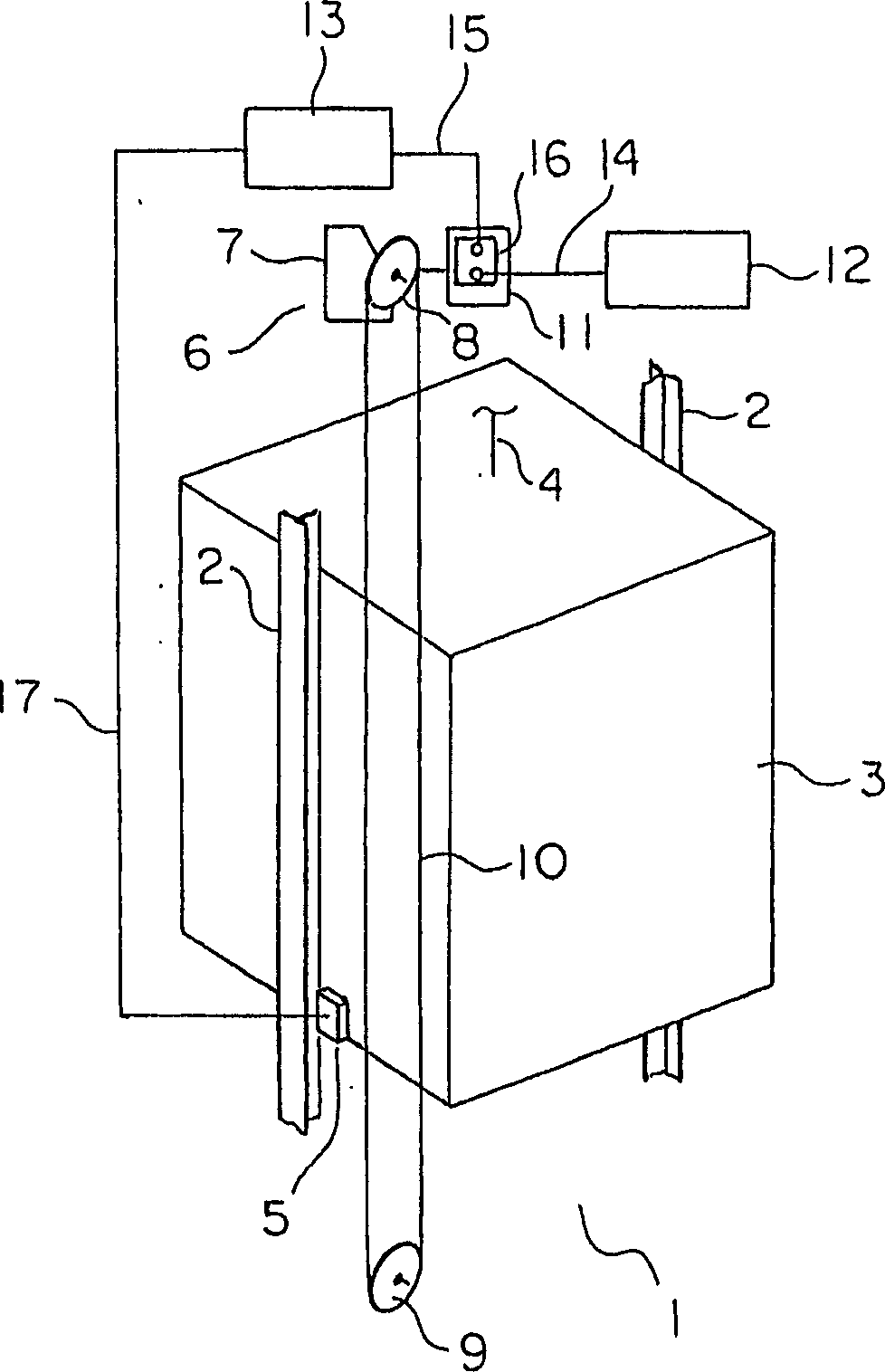
[0023] figure 1 It is a configuration diagram schematically showing the elevator apparatus according to Embodiment 1 of the present invention. In the drawing, a pair of car guide rails 2 is provided in a hoistway 1 . The car 3 is guided by the car guide rail 2 to move up and down in the hoistway 1 . A traction machine (not shown) for raising and lowering the car 3 and a counterweight (not shown) is arranged at an upper end portion of the hoistway 1 . The main rope 4 is wound around the driving sheave of the traction machine. The car 3 and the counterweight are suspended in the hoistway 1 by the main rope 4 . On the car 3, a pair of guide rail engaging portions 5 serving as braking means are arranged to face the respective car guide rails 2 . The car 3 is braked by the action of each guide rail engaging portion 5 .
[0024] In addition, a speed governor 6 serving as car speed detection means for detecting the ascending and descending speed of the car 3 is arranged at the u...
Embodiment approach 2
[0042] Figure 6 It is a front view showing the elevator apparatus according to Embodiment 2 of the present invention, Figure 7 yes means Figure 6 Side view of the elevator installation in . In this example, each guide rail engagement portion 5 is arranged in a groove portion 65 at the upper end of the longitudinal frame 63 . Other configurations and operations are the same as those in Embodiment 1.
[0043] In such an elevator apparatus, the safety link conventionally attached to the car can be omitted, and each guide rail engaging portion 5 can be arranged within the length of the car 3 in the height direction. Therefore, the length in the height direction of the elevating main body including the car 3 can be shortened, and space saving of the entire elevator apparatus can be realized.
Embodiment approach 3
[0045] Figure 8 is a front view showing an elevator apparatus according to Embodiment 3 of the present invention, Figure 9 yes means Figure 8 Side view of the elevator installation in . In this example, each rail engaging portion 5 is provided in a groove portion 65 in the middle portion of the vertical frame 63 . Other configurations and operations are the same as those in Embodiment 1.
[0046] As in Embodiments 1 and 2, also in such an elevator apparatus, space-saving of the entire elevator apparatus can be realized.
PUM
 Abstract
Description
Claims
Application Information