Short arc type discharge lamp

A discharge lamp and arc light technology, applied in the direction of discharge lamps, gas discharge lamps, high-pressure discharge lamps, etc., can solve the problems of lamp breakage, breakage, and inability to prevent breakage flexibly relative to the lamp

Active Publication Date: 2010-06-23
ORC MFG
View PDF5 Cites 0 Cited by
  • Summary
  • Abstract
  • Description
  • Claims
  • Application Information

AI Technical Summary

Problems solved by technology

Although it is possible to qualitatively avoid lamp breakage, it is impossible to quantitatively judge how much margin there is in the mechanical strength until the breakage of the internal pressure of the lamp.
This implies that protection against lamp breakage may not be guaranteed in environments where lamp design specifications change frequently
[0013] For example, the shape of the cracked area thought to be directly related to cracking (diameter of the glass member, from the end of the bulb to the sealing part) is designed by adopting dimensions that are estimated to be no problem according to empirical rules, including the rise characteristic of the lamp, and the like. The length of the front end, the thickness of the sealing glass), and when trying to light it, it is found that due to the amount of mercury enclosed in the lamp and the size of the lamp, unexpected cracks often occur
Therefore, in the methods of avoiding cracks seen in these prior art, since the pressure resistance until cracking is qualitative, there is still a problem of not being able to flexibly prevent cracking with respect to the specification of the lamp

Method used


Image

  • Short arc type discharge lamp
  • Short arc type discharge lamp
  • Short arc type discharge lamp

Examples


Embodiment Construction

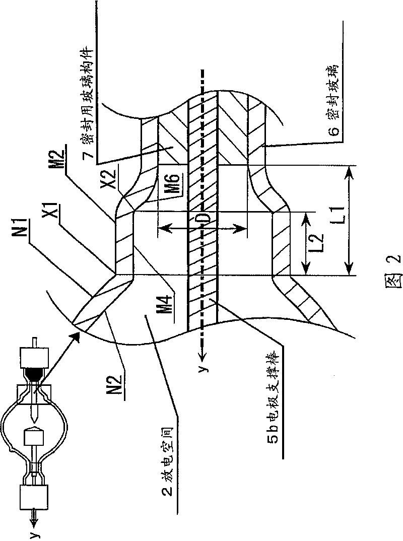
[0029] An embodiment of the present invention is a short-arc type discharge lamp with an internal pressure of 2.0 to 3.0 MPa when it is lit. The dimension from the end of the spherical surface of the luminous tube to the front end of the sealing part is set as L1 (mm), and The diameter of the sealing glass member is set to D (mm), and when the internal pressure of the lamp is set to P (MPa), the relationship D<(-0.38×P+1.79)×L1+(-3.32×P+24.3 ), in the range L2 from the spherical end X1 of the arc tube to the intersection point X2 of two different curvatures on the inner surface of the lamp, the thickness t of the sealing glass is 3.0mm≦t≦5.0mm.

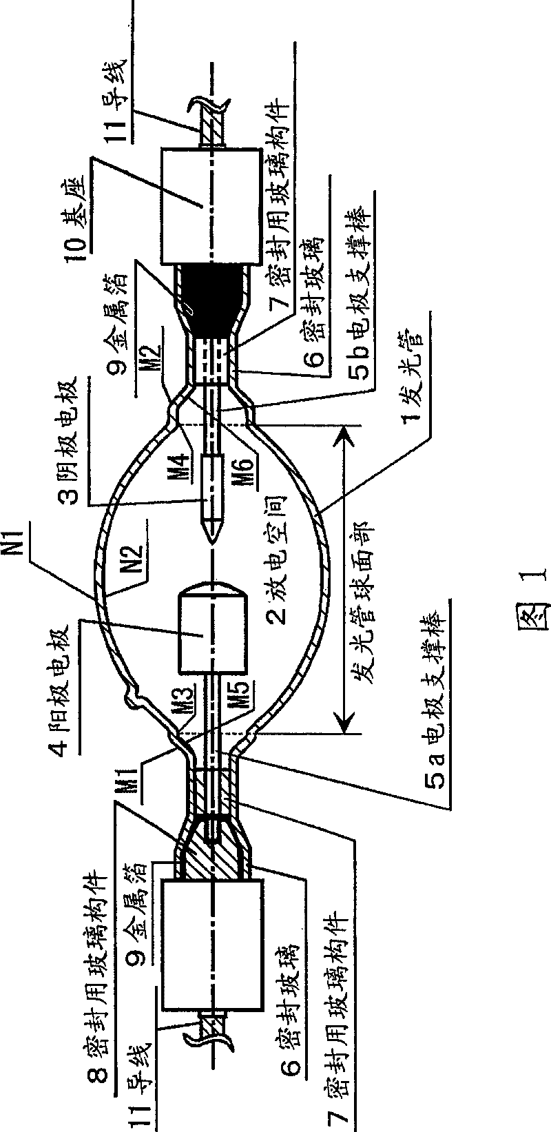
[0030] figure 1 It is a conceptual diagram of a short-arc type discharge lamp in an embodiment of the present invention. figure 2 It is a partially enlarged schematic diagram of the cathode electrode side of a short-arc discharge lamp. exist figure 1 and figure 2Among them, the luminous tube 1 is a glass bulb of a short-arc di...


PUM


Abstract

Provided is a short-arc type discharge lamp. To avoid explosion at lighting while satisfying build-up characteristics, irradiation illuminance characteristics, and life characteristics, as to a short-arc type discharge lamp with an inner pressure at lighting of 2.0 to 3.0 MPa. A negative electrode (3) and a positive electrode (4) are arranged in a discharge space (2) inside a light-emitting tube (1) of the short-arc type discharge lamp. Rare gas and mercury are sealed in inside the discharge space (2). Provided a dimension from the end of a spherical part of the light-emitting tube to the tipof a sealing glass member (7) is L1 (mm), a diameter of the sealing glass member (7) is D (mm), and an inner pressure at lamp operation is P (Mpa), a shape of the lamp is determined to satisfy: D<(-0.38*P+1.79)*L1+(-3.32*P+24.3). Furthermore, the thickness t of a sealing glass (6) is 3.0 mm<=t<=5.0 mm, within range L2 of from the end of a spherical part of the light emitting tube X1 to the intersection point X2 of different two curvatures in the inside of the lamp. The power supply to the lamp is in a range of 5 to 25 kW.

Description

technical field [0001] The present invention relates to a short-arc discharge lamp, in particular to a short-arc discharge lamp which is used as a light source in the exposure process of semiconductor and liquid crystal manufacturing and has a switching power equal to or greater than 1 kW. Background technique [0002] In an exposure process such as a manufacturing process, a short-arc discharge lamp used as a light source is required to have a high illuminance. It is known that such short-arc discharge lamps (hereinafter referred to as lamps) generally have a switching power greater than or equal to 1 kW, and the temperature and internal pressure during lighting are quite high. As one method for realizing the above-mentioned high illuminance, there is a method of enclosing a large amount of mercury, a rare gas, etc. to improve the luminous efficiency of the lamp in the ultraviolet region. In this case, there is a problem that the lamp internal pressure at the time of light...

Claims


Application Information

Patent Timeline
Patent Type & Authority Patents(China)
IPC IPC(8): H01J61/00H01J61/30H01J61/86H01J61/88
CPCH01J9/247H01J9/266H01J61/12H01J61/30H01J61/33H01J61/86
Inventor 加濑征彦泽俊行桑畑宏仓野正宏
Owner ORC MFG
Why Eureka
Try Eureka