

Injector
A technology of injectors and injection valves, which is applied to fuel injection devices, special fuel injection devices, machines/engines, etc., and can solve problems such as high-pressure fuel leakage
- Summary
- Abstract
- Description
- Claims
- Application Information
AI Technical Summary
Problems solved by technology
Method used
Image

Examples
example 1
[0024] (Structure of Example 1)
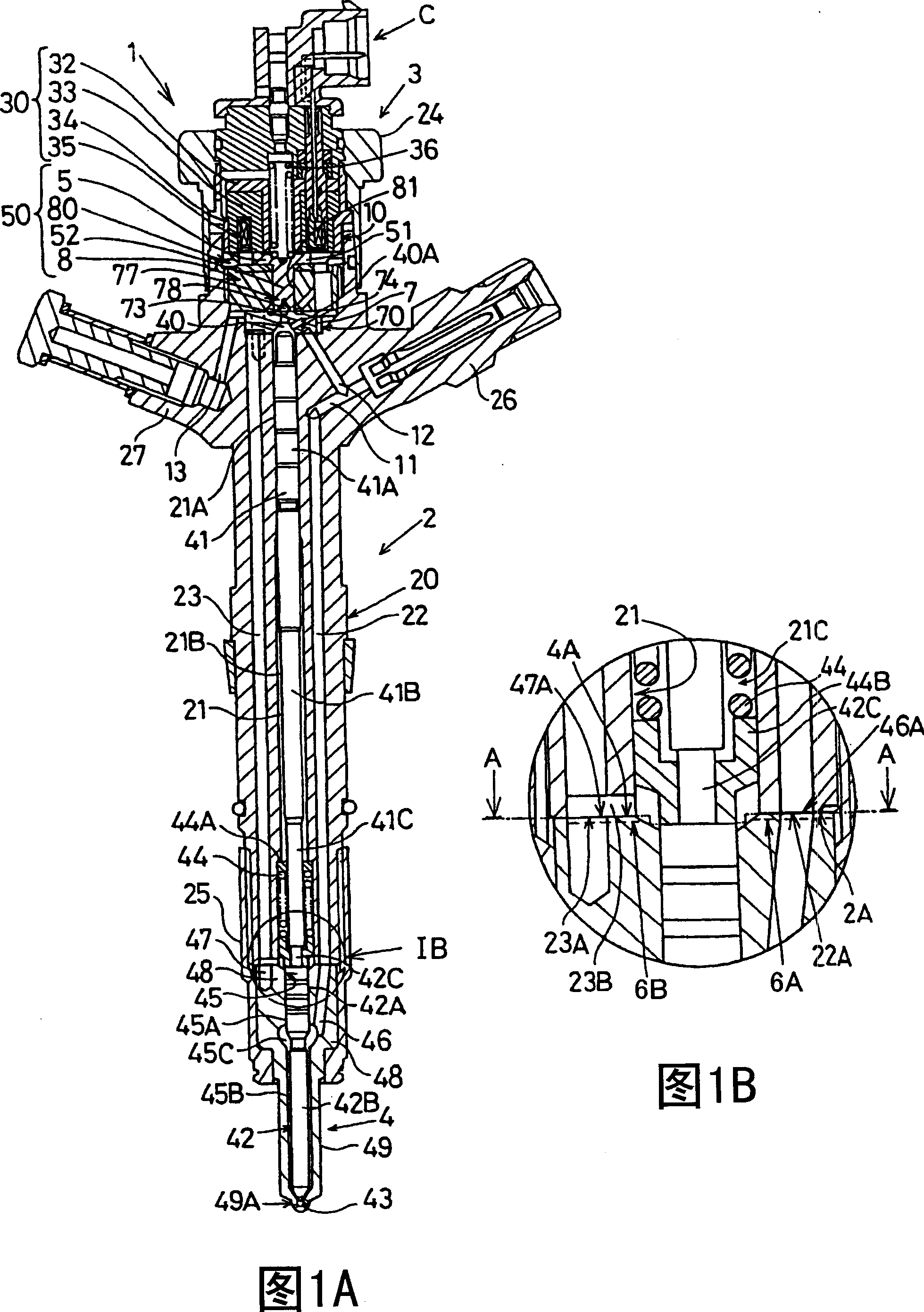
[0025] FIG. 1A shows an electromagnetic control type fuel injection valve 1 for intermittently injecting fuel into a combustion chamber of an engine, and FIG. 1B shows a metal sealing structure of a main part of the fuel injection valve 1 .
[0026] The fuel injection valve 1 is used in an accumulator type (common rail type) fuel injection device of a diesel engine and injects high-pressure fuel input from a common rail (not shown) to a combustion chamber of the engine.
[0027] The fuel injection valve 1 includes an injection valve body 2 , a solenoid valve 3 (corresponding to a driving device and including a piezoelectric type) connected to the upper end of the injection valve body 2 , and a nozzle 4 fixed to the lower end of the injection valve body 2 . The solenoid valve 3 includes a connector C connected to wiring from an engine control unit (ECU) (not shown) and is controlled by a control signal from the ECU.
[0028] The injection valv...
example 2
[0056] (Structure of Example 2)
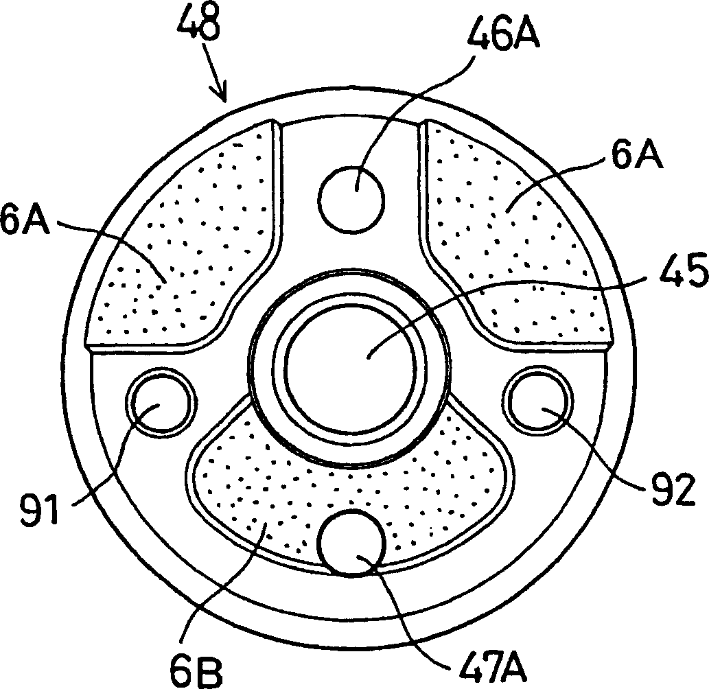
[0057] image 3 The metal sealing surface of the back end surface 4A of Example 2 of the present invention is shown. Example 2 differs from Example 1 in that an external recess 6A is provided so that the bore reaches a position where an extension line from the center of the syringe 45 to the high-pressure fuel hole 46A intersects the outermost boundary. Therefore, only the vicinity of the high-pressure fuel hole 46A becomes a sealing surface, and not the vicinity of the high-pressure fuel hole 46A becomes a depression communicating with the outer peripheral portion.
[0058]Under this structure, the seal surface includes a seal surface portion of the adjacent portion centered on the high-pressure fuel hole 46A and a seal surface portion centered on the low-pressure fuel hole 47A and having almost half of the outer peripheral boundary. Therefore, the sealing surface can utilize a smaller area to play a sealing role. In particular, the vicini...
example 3
[0063] (Structure of Example 3)
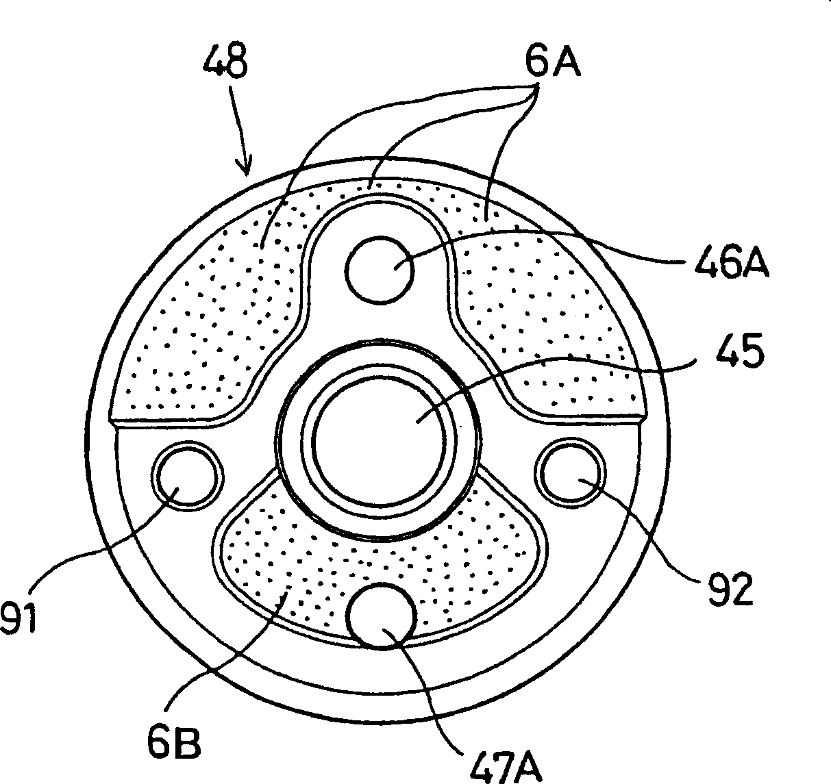
[0064] Figure 4 show image 3 The metal sealing structure of the back end face 4A. The retaining sealing surface 46B is provided in the recess 6A of Example 2, which is formed by boring in an area other than the vicinity of the high-pressure fuel hole 46A. The holding sealing surface 46B has a quarter-sector shape as high as the outer peripheral boundary symmetrically with respect to the high-pressure fuel hole 46A, and is separated from the vicinity of the high-pressure fuel hole 46A by retaining a portion of the recess 6A of Example 2.
[0065] This structure makes the vicinity of the high-pressure fuel hole 46A and the retaining sealing surface 46B connected to the outer peripheral boundary become a flat metal sealing surface, forming a sealing surface that receives axial force uniformly.
[0066] In this structure, except for the sealing surface adjacent to the high-pressure fuel hole 46A, the surface pressure is slightly lowered due t...
PUM
 Abstract
Description
Claims
Application Information