Novel dual-mass flywheel torsion damper

A dual-mass flywheel and torsional shock absorber technology, applied in flywheels, counterweights, etc., can solve problems such as the difficulty in meeting the lightweight requirements of automobiles, the difficulty in wiring electronically controlled variable inertia systems, and the large amount of magnetorheological fluid used to achieve easy Layout and implementation, reduced sealing technology requirements and processing, high controllability effect

Active Publication Date: 2021-03-16
JILIN UNIV
View PDF10 Cites 1 Cited by
  • Summary
  • Abstract
  • Description
  • Claims
  • Application Information

AI Technical Summary

Problems solved by technology

In the above technical solutions, the axial dimension is large and difficult to arrange; the weight is too large to meet the lightweight requirements of automobiles; the amount of magnetorheological fluid is large, which not only increases the cost of manufacturing, but also has a relatively large impact on the processing technology and sealing technology. High requirements; electronically controlled variable inertia system is difficult to wire and other defects

Method used


Image

  • Novel dual-mass flywheel torsion damper
  • Novel dual-mass flywheel torsion damper
  • Novel dual-mass flywheel torsion damper

Examples


Embodiment Construction

[0090] The present invention will be further described in detail below in conjunction with the accompanying drawings, so that those skilled in the art can implement it with reference to the description.

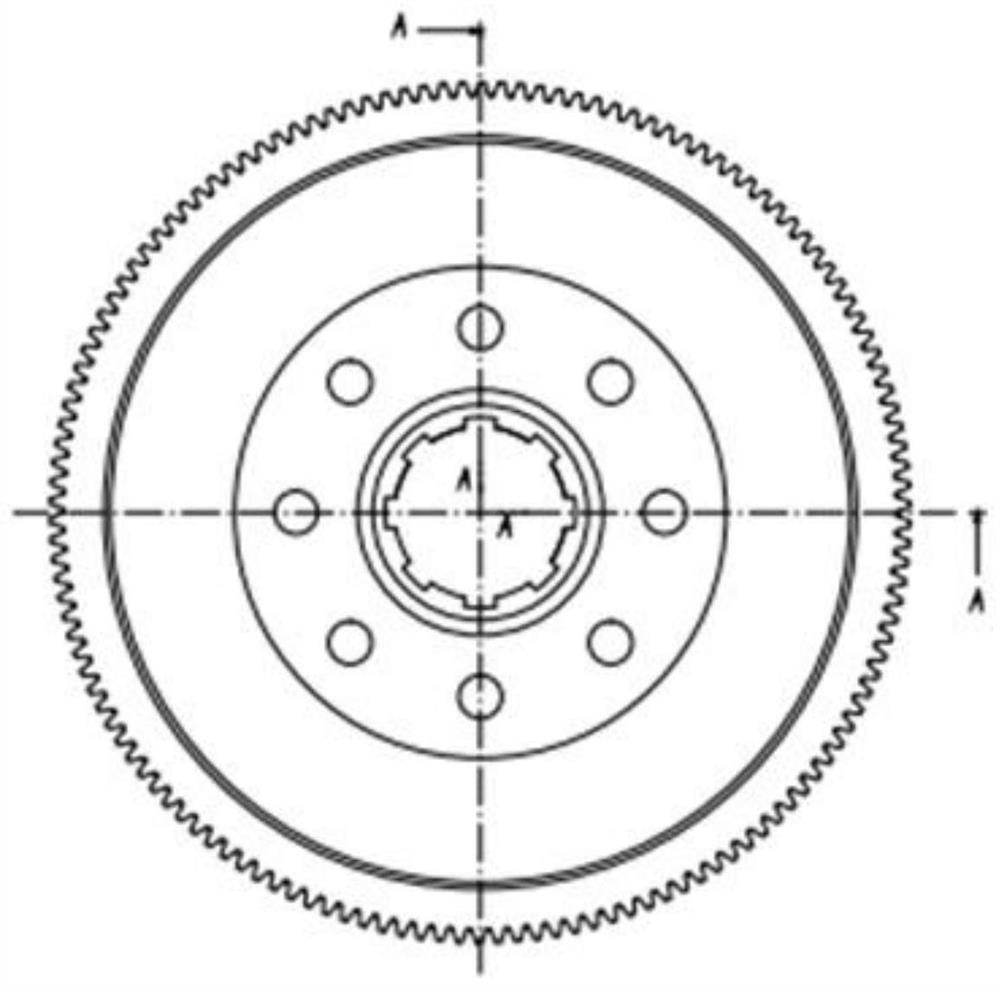
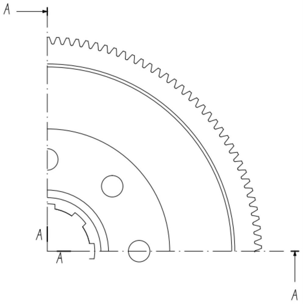
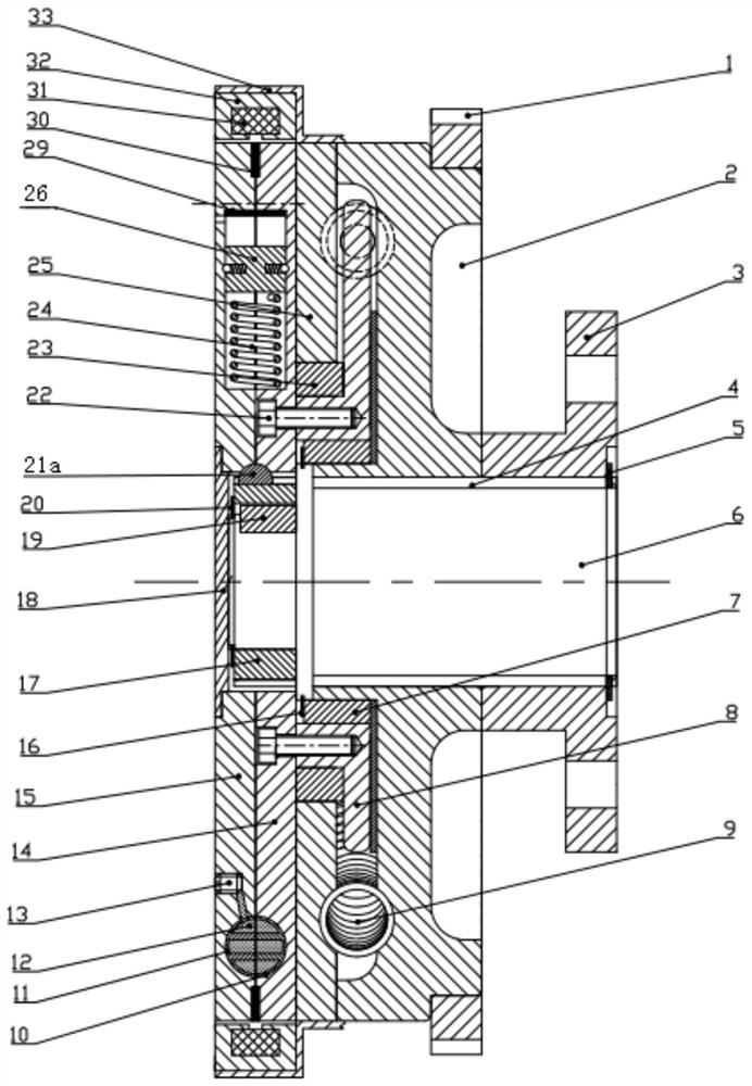
[0091] Such as Figure 1-19 As shown, the present invention provides a novel dual-mass flywheel torsional damper, which mainly includes: starting ring gear 1; driving flywheel 2; driving flywheel arc groove 2a; connecting flange 3; spline 4; Spring 5; transmission shaft 6; sliding bearing 7; force transmission plate 8; variable pitch arc spring 9; first half liquid flow channel body 10; second half liquid flow channel body 11; magnetorheological fluid 12; oil plug 13 ; Inner driven flywheel 14; Outer driven flywheel 15; Shoulder spring 16; Transmission gear 17; Connecting bolt 22; sliding bearing 23; straight spring 24; sealing plate 25; sealing plate arc groove 25a; additional mass block 26; steel ball spring 27; steel ball 28; Yoke 32; fixed bracket 33; first piston 34a; ...


PUM


Abstract

The invention discloses a novel dual-mass flywheel torsion damper. The novel dual-mass flywheel torsion damper comprises a transmission shaft, a driving flywheel, a transmission gear, a driven flywheel, a force transmission device, a first liquid storage cavity, a second liquid storage cavity, a first rack, a second rack, two first pistons, two second pistons and an excitation device, wherein thedriven flywheel is coaxially arranged on the transmission gear in an empty sleeving manner. The force transmission device is used for transmitting power from the driving flywheel to the driven flywheel. The first liquid storage cavity and the second liquid storage cavity are separately formed in the driven flywheel and are symmetrically arranged. The first rack and the second rack are movably arranged in the driven flywheel and are in engaged transmission with the transmission gear. The two first pistons are fixedly connected to the two ends of the first rack separately. The two second pistonsare fixedly connected to the two ends of the second rack separately. First piston containing cavities and second piston containing cavities are formed in the two ends of the first liquid storage cavity and the two ends of the second liquid storage cavity correspondingly. The two first pistons are separately arranged in the two first piston containing cavities in a matched mode, and the two secondpistons are separately arranged in the two second piston containing cavities in a matched mode. The excitation device is coaxially sleeved on the outer circumference of the driven flywheel in an empty manner.

Description

technical field [0001] The invention belongs to the technical field of torsional vibration damping components in automobile power transmission systems, and in particular relates to a novel double-mass flywheel torsional vibration damper. Background technique [0002] With the development and application of new automotive technologies such as light-weight, low-speed, high-torque engines and passenger car diesel engines, the torsional vibration of the power train produced by the speed fluctuations of automotive engines is becoming more and more difficult to control. Traditional automobiles limit the torsional vibration of the drive train by installing a torsional shock absorber in the clutch driven disc, but due to the limitation of size and layout space, the elastic elements of the clutch torsional shock absorber are often short in length, high in stiffness, and small in relative rotation angle , resulting in poor torsional vibration damping effect, reducing the service life ...

Claims


Application Information

Patent Timeline
Patent Type & Authority Applications(China)
IPC IPC(8): F16F15/30F16F15/31F16F15/28
CPCF16F15/28F16F15/30F16F15/31
Inventor 史文库曲俊龙陈志勇张曙光张恒海
Owner JILIN UNIV
Why Eureka
Try Eureka