Fuel injector reducing stress concentration

A technology of fuel injectors and injectors, applied in the direction of fuel injection devices with stress-reducing measures, fuel injection devices, special fuel injection devices, etc., capable of solving problems such as high-pressure fuel leakage, separation of nozzle bodies, and complex structures

Inactive Publication Date: 2006-07-19
DENSO CORP
View PDF1 Cites 4 Cited by
  • Summary
  • Abstract
  • Description
  • Claims
  • Application Information

AI Technical Summary

Problems solved by technology

However, in this configuration, the nozzle body needs to be separated
Accordingly, there arises another problem that the structure becomes complicated and high-pressure fuel easily leaks from the sealing surface

Method used


Image

  • Fuel injector reducing stress concentration
  • Fuel injector reducing stress concentration
  • Fuel injector reducing stress concentration

Examples


Embodiment Construction

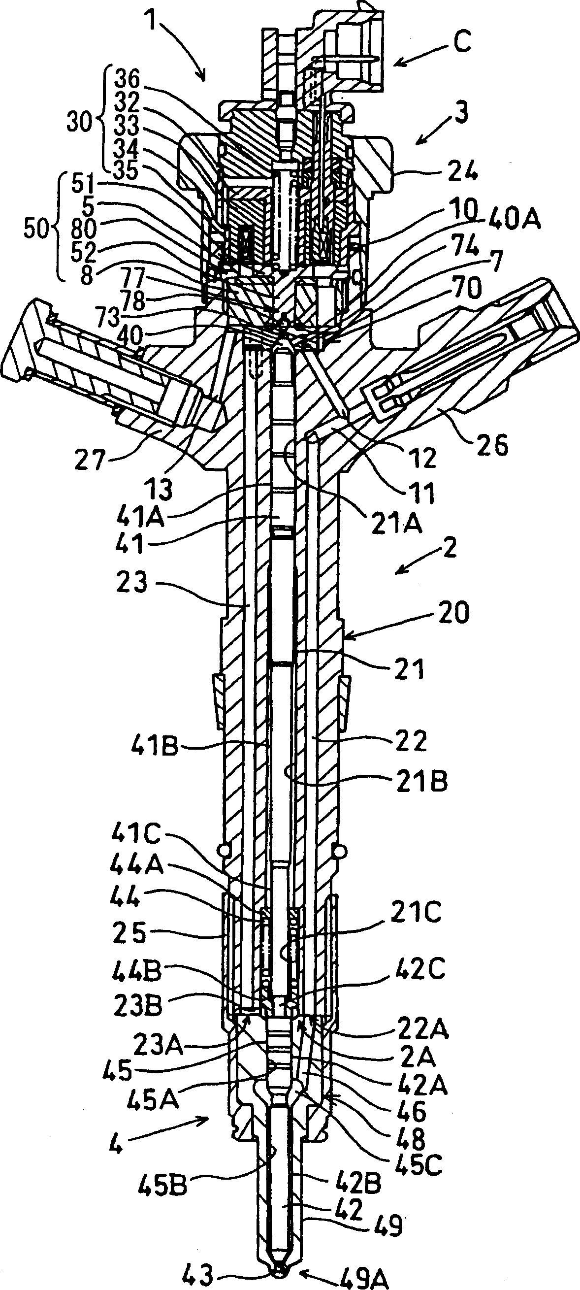
[0029] refer to figure 1 , which shows an electromagnetically controlled fuel injector (such as a piezoelectric fuel injector) 1 that intermittently injects fuel into the combustion chamber of the engine. The fuel injector 1 is used in an accumulator type (common rail type) fuel injection device of a diesel engine, and injects high-pressure fuel from a common rail (not shown) into a combustion chamber of the engine. The injector 1 has an injector body 2 , a solenoid valve 3 mounted on an upper end side of the injector body 2 , and a fuel injection nozzle 4 fixed to a lower end side of the injector body 2 .

[0030]The solenoid valve 3 has a connector C connected to a wire harness extending from an engine control unit (ECU) (not shown). The solenoid valve 3 is controlled by a control signal output from the ECU.

[0031] The injector body 2 has a valve body 20 formed in a rod shape. The valve body 20 is formed with a barrel 21 passing through the axial center, and a high-pre...


PUM


Abstract

On an inner wall of a bag-shaped hole portion (45C) of a nozzle body (48), a cross angle between the bag-shaped hole portion (45C) and a needle hole (45) or an oblique high-pressure fuel passage (46) of the nozzle body (48) is made obtuse, i.e. at 90 degrees or larger, through an electrochemical machining process with a suitably-shaped electrode (G) or through after-processing with a boring tool (H) having a predetermined shape. The center of the bag-shaped hole portion (45C) may be deviated toward the high-pressure fuel passage (46) or the high-pressure fuel passage (46) may be connected to a maximum diameter portion of the bag-shaped hole portion (45C) to provide the obtuse cross angle. Thus, excessive stress on the inner wall of the bag-shaped hole portion (45C) or a breakage of the nozzle body (48) due to a crack can be inhibited.

Description

technical field [0001] The present invention relates to a fuel injector for injecting high-pressure fuel into a combustion chamber of an internal combustion engine, the high-pressure fuel being pressurized by means of a high-pressure feed pump and stored under pressure in a common rail. Background technique [0002] The fuel injector is used in an accumulator-type fuel injection device of a diesel engine or the like to inject high-pressure fuel from a common rail into a combustion chamber of the engine. The fuel injector has: an injector main body provided with a nozzle provided on its front end side; a driving device such as a solenoid valve and the like provided on a rear end side of the injector main body. The driving device receives a control signal from an engine control unit (ECU) to move a control piston provided in an injector body and a needle valve provided in a nozzle, thereby opening or closing a fuel injection hole of the nozzle. The on / off control adjusts the ...

Claims


Application Information

Patent Timeline
Patent Type & Authority Applications(China)
IPC IPC(8): F02M51/06
CPCF02M61/168F02M47/027F02M61/12F02M2200/8069F02M55/008F02M2200/03
Inventor 东条千太正垣好朗稻叶学
Owner DENSO CORP
Why Eureka
Try Eureka