Steel cord for rubber track main cord

A technology of rubber crawler and steel cord, which is applied to the reinforcement layer of pneumatic tires, transportation and packaging, tire parts, etc., can solve the problems of low immersion of core wire 82C, increased weight of steel cord 90, narrow gap, etc.

Inactive Publication Date: 2006-07-19
BRIDGESTONE CORP
View PDF6 Cites 0 Cited by
  • Summary
  • Abstract
  • Description
  • Claims
  • Application Information

AI Technical Summary

Problems solved by technology

[0004] But when Figure 5 In the structure as shown, since the space between the sheath yarns 82S constituting the core strand 82 is narrow, the penetration of the rubber into the core yarn 82C constituting the core strand 82 is low.
For this reason, when the rubber crawler belt having the steel cord 80 is used, a load is repeatedly applied, and as a result, such a defect occurs that the core wire 82C constituting the core strand 82 runs from the end of the steel cord 80 to the rubber crawler belt. side of the surface protruding
[0007] However, as disclosed in Japanese Patent Application Laid-Open No. 2001-20188 Image 6 In the case of a structure as shown, the diameter of the core wire 92C and the core wire 96C is large
For this reason, there arises a problem that the weight of the steel cord 90 itself increases
In addition, since the rigidity of the steel cord 90 is increased, it is difficult to bend when manufacturing rubber products using a rubber crawler having the steel cord 90, and there is also a problem that it is necessary to manufacture without peeling at the seam.
In addition, when using wire wound on a bobbin of the same shape as the core wire and the sheath wire, the winding lengths are different due to the difference in diameter of the wire, so when using wires with different diameters, a wire with a smaller diameter may be generated. Problems such as margin (loss) and unprofitable cost increase

Method used


Image

  • Steel cord for rubber track main cord
  • Steel cord for rubber track main cord
  • Steel cord for rubber track main cord

Examples


no. 1 Embodiment approach

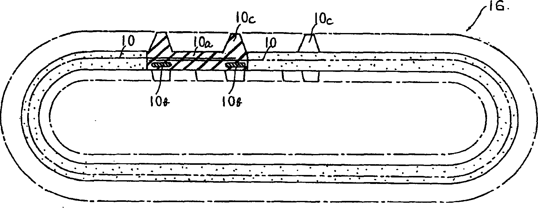
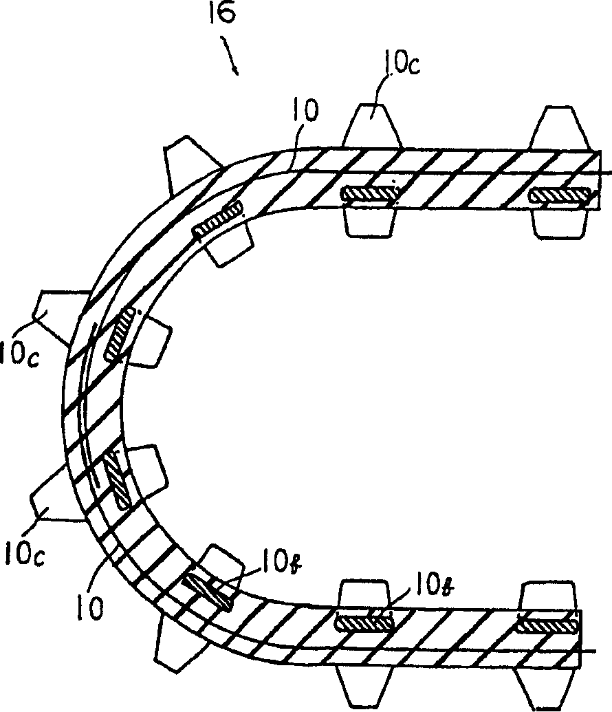
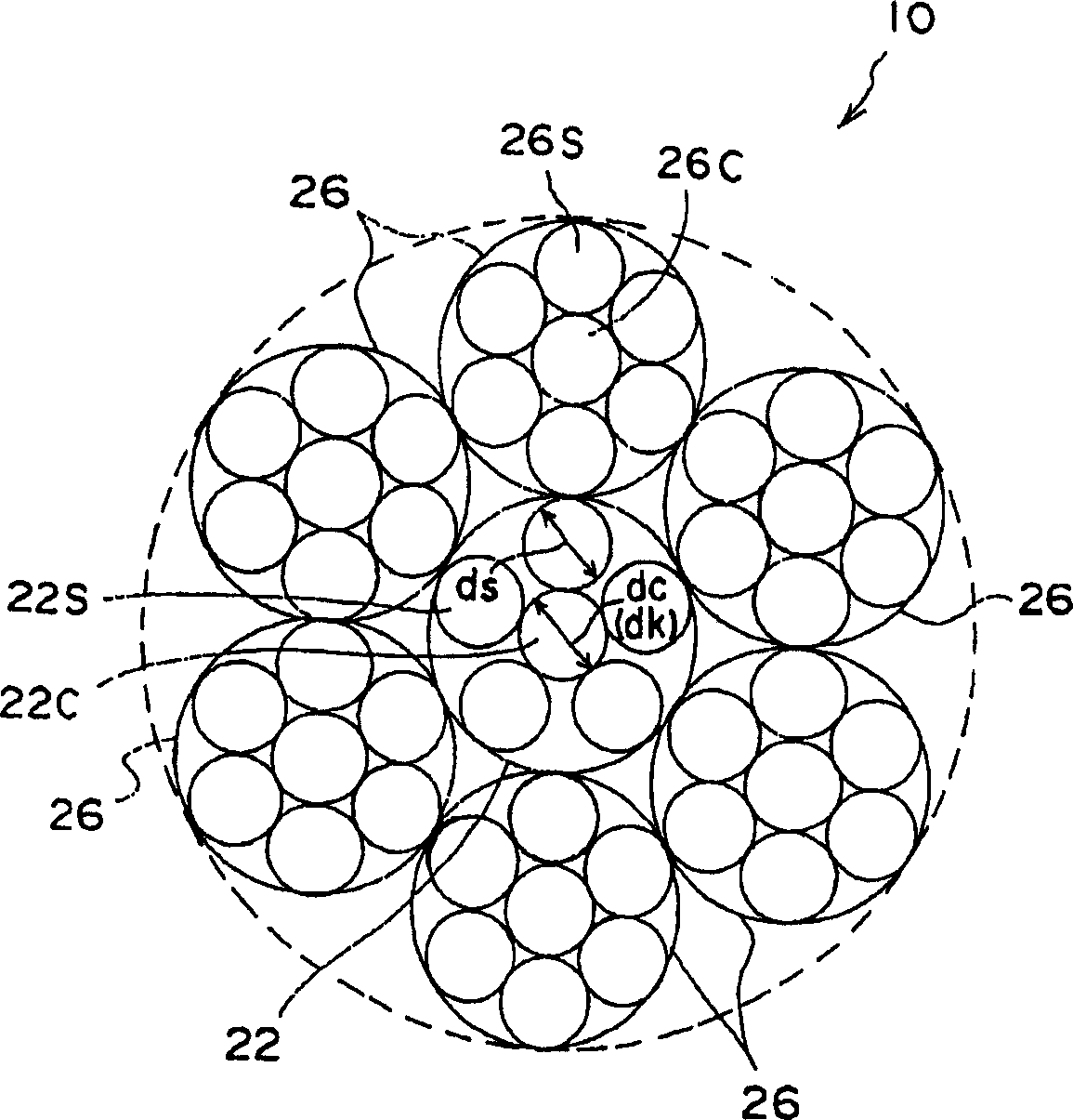
[0028] First, the first embodiment will be described. Such as Figure 1 ~ Figure 3 As shown, the steel cord 10 of the first embodiment is embedded in a rubber track 16 (refer to figure 1 , figure 2 ) in the length direction to serve as steel cords for reinforcing members (main cords). The steel cord 10 is composed of one core strand 22 and six sheath strands 26 twisted around the core strand 22 . The rubber track 16 is initially formed in a jointed belt shape in which both ends of the steel cord 10 protrude. In order to form a jointless loop, a new rubber material 16a is filled with the two ends of the steel cord 10 overlapped and Perform vulcanization molding. In addition, 16b is a core bar embedded in rubber at the same time, and 16c is a plate tooth formed on the outer peripheral side.

[0029] Such as image 3 As shown, the core strand 22 is composed of one core wire 22C and five sheath wires 22S twisted around the core wire 22C. Each of the sheath strands 26 is c...

no. 2 Embodiment approach

[0032] Next, a second embodiment will be described. In the second embodiment, the same reference numerals are attached to the same components as those in the first embodiment, and description thereof will be omitted.

[0033] Such as Figure 4 As shown, the steel cord 30 of the second embodiment is composed of one core strand 32 and six sheath strands 26 twisted around the core strand 32 .

[0034] The core portion 32C of the core strand 32 is composed of three core wires 32C1 to C3 twisted with each other. Thereby, the surface area of ​​the core part 32C can be enlarged, and the impregnation property of the rubber into the core part 32C can be further improved. In addition, in this case, the diameter dk of the core portion 32C (refer to Figure 4 ) is the same as the diameter of the projected locus of the core 32C in the cord length direction.

[0035] As mentioned above, although an Example was given and demonstrated embodiment of this invention, these Examples are only ...

experiment example

[0037] Rubber crawlers using four types of steel cords as steel cords for reinforcement, the steel cord 10 (Example 1), The steel cord 30 (Example 2) described in the above-mentioned second embodiment, the steel cord composed of one core strand and four sheath strands (comparative example), the conventional steel cord (conventional example) . The test condition is 200 hours of walking with rubber tracks. Table 1 shows the core strand structures and filament diameters of Example 1, Example 2, Comparative Example, and Conventional Example (core strand diameter dc of core strand, sheath filament ds of core strand, core portion of core strand) diameter dk) and test results.

[0038] Example 1

Example 2

comparative example

Past example

Core Strand Construction

1+5

3+5

1+4

1+6

Core wire diameter dc(mm)

0.34

0.16

0.34

0.34

Core wire sheath wire diameter ds(mm)

0.34

0.34

...


PUM


Abstract

A steel cord for a rubber track main cord, where core filaments of a core strand is restricted from coming out of a rubber member. This is achieved by causing rubber to penetrate to core filament surfaces of the core strand without reducing a cord breaking load. A core strand (22) of a steel cord (10) is constituted of one core filament (22C) and five sheath filaments (22S) twisted around the core filament (22). Six sheath strands (26) are twisted around the core strand (22). A rubber member is highly penetratable into the core filament (22C) because sufficiently wide gaps are held between the sheath filaments (22S). The structure above realizes the steel cord (10) where the core filament (22C) is restricted from coming out.

Description

technical field [0001] The present invention relates to a steel cord for a main cord built into a rubber crawler. Background technique [0002] Steel cords are often used as reinforcing materials for jointless endless rubber tracks. In addition, in order to improve the load-bearing capacity of the steel cord, the structure of the steel cord is often adopted with a 7×7 structure that increases the cord cutting load. [0003] As the 7×7 structure, for example, Japanese Patent Laying-Open No. 11-093087 discloses such as Figure 5 Like the steel cord 80 shown, six sheath strands 86 are arranged around one core strand 82. The diameters of the core wire 86C and the sheath wire 86S of 86 are all the same. [0004] But when Figure 5 In the structure as shown, since the space between the sheath yarns 82S constituting the core strand 82 is narrow, penetration of the rubber into the core yarn 82C constituting the core strand 82 is low. For this reason, when the rubber crawler belt ...

Claims


Application Information

Patent Timeline
Patent Type & Authority Applications(China)
IPC IPC(8): D07B1/06B60C9/00
CPCD07B2201/2024D07B1/0613D07B2201/1032D07B2201/102D07B2401/208D07B2501/2046D07B2201/2059D07B2201/2023D07B2201/2061D07B2201/1028D07B2201/104D07B2201/2006D07B2201/2039D07B1/0626D07B2801/12D07B2801/24D07B2801/14D07B1/0633D07B2201/1064D07B2501/20
Inventor 增渕英树
Owner BRIDGESTONE CORP
Why Eureka
Try Eureka