Device for delivery motion switch to bicycle driving device

A technology of transmission and movement, which is applied in the direction of wheel transmission, bicycle accessories, bicycle gear transmission mechanism, etc., and can solve the problems of hindering the arrangement of fast tensioning devices

Active Publication Date: 2006-07-26
SRAM
View PDF2 Cites 14 Cited by
  • Summary
  • Abstract
  • Description
  • Claims
  • Application Information

AI Technical Summary

Problems solved by technology

This results in a mounting position corresponding to the cable extension, aligned wit

Method used


Image

  • Device for delivery motion switch to bicycle driving device
  • Device for delivery motion switch to bicycle driving device

Examples


Embodiment Construction

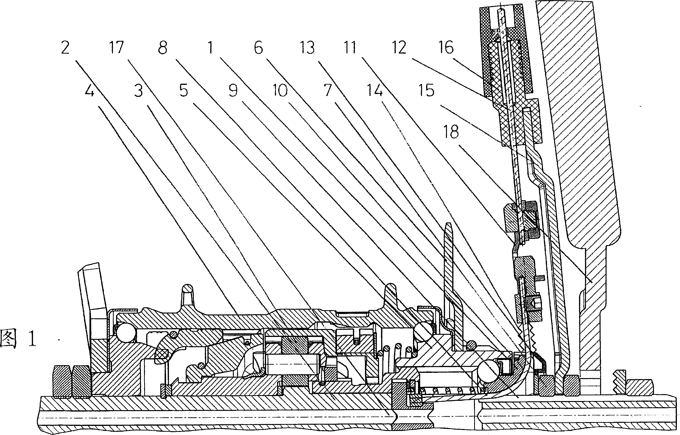
[0019] FIG. 1 shows a multi-speed transmission sleeve with a device for transmitting a switching movement between a bearing cone 1 and a shaft 2 . The multi-speed transmission sleeve consists of a sleeve 4 surrounding the transmission 3 which rotates about a shaft 2 fixed at the outer end of the frame. A ball bearing is arranged on both sides of the sleeve 4 , wherein one side of the inner ball raceway is arranged on a rotation-proof structure of the shaft 2 . The sleeve 4 rests flanking on a drive 5 , which likewise rests rotatably on the bearing cone 1 . The wing 6 is secured against rotation on the drive 5 and is axially secured with a tensioning ring. The bearing cone 1 is arranged on the shaft 2 in a rotationally fixed manner, so that the shaft 2 is shaped, or its circumference is flattened at two opposite points, and the inner contour of the bearing cone 1 is adjusted accordingly. The transmission element moving linearly from the converter is in the form of a steel cab...


PUM


Abstract

The invention relates to the transmission of switching movements into a multi-speed transmission. The switching rod or a steel cable section is introduced into the sleeve drive from the outside, ie between the wing and the outer end of the frame, through an opening extending axially between the bearing cone and the shaft. The linear switching movement on the cable is thus transmitted directly and without conversion to the transmission. In order to guide the steel cable in the sleeve, a groove is provided on the bearing cone and/or on the inner diameter of the bearing cone. The cables are deflected from the axial direction to the frame into cable guide grooves of convex profile on a fixed element, preferably on the bearing cone or on the shaft.

Description

technical field [0001] The invention relates to a device for introducing and subsequently transmitting a shifting movement in a bicycle transmission, in particular to a device for axial displacement of transmission and clutch elements in a multi-speed sleeve transmission according to the preambles of the independent claims installation. Background technique [0002] A multi-speed sleeve is formed from at least one planetary gear set arranged around the fixed shaft. The rotational torque is transmitted via a wing to the drive and via one of the transmission paths of the planetary gear to the sleeve housing. The corresponding selected transmission path is implemented by a component of the transmission, which rotates or moves relative to the shaft. The gear is selected via a switch in the region of the guide rod and is further guided, for example mechanically, by a linear movement of a steel cable to the multi-speed sleeve. The shifting movement corresponding to the selected...

Claims


Application Information

Patent Timeline
IPC IPC(8): B62M11/04
CPCB62M11/16B62M25/02
Inventor 沃纳·斯托尔迈克儿·科豪普特甘特·裴斯卡尔·约阿希姆·屈内
Owner SRAM
Why Eureka
Try Eureka