Connecting structure of multi-ring drum drying machine

A technology of drum dryer and connection structure, which is applied in non-progressive dryers, dryers, drying solid materials, etc., and can solve problems such as body damage, deformation, welding cracking, etc.

Inactive Publication Date: 2006-07-26
卢英林
View PDF0 Cites 12 Cited by
  • Summary
  • Abstract
  • Description
  • Claims
  • Application Information

AI Technical Summary

Problems solved by technology

If the pillars connecting the multi-ring drums are all fixedly welded, the thermal pressure caused by the thermal deformation difference between the drums may cause welding cracks or serious deformation, resulting in damage to the machine body

Method used


Image

  • Connecting structure of multi-ring drum drying machine
  • Connecting structure of multi-ring drum drying machine

Examples


Embodiment Construction

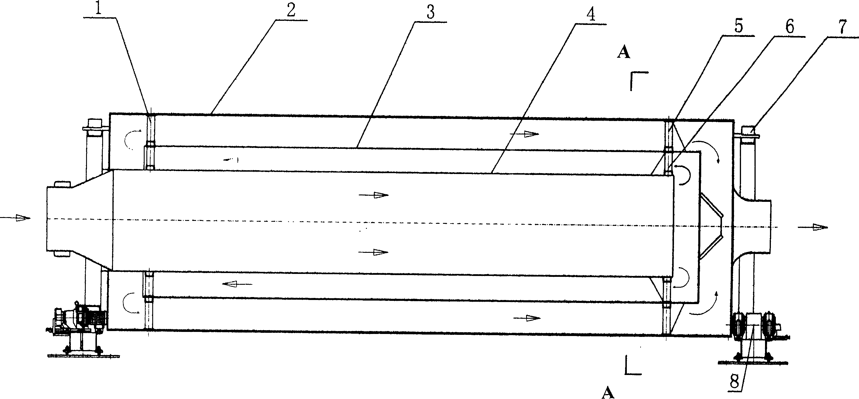
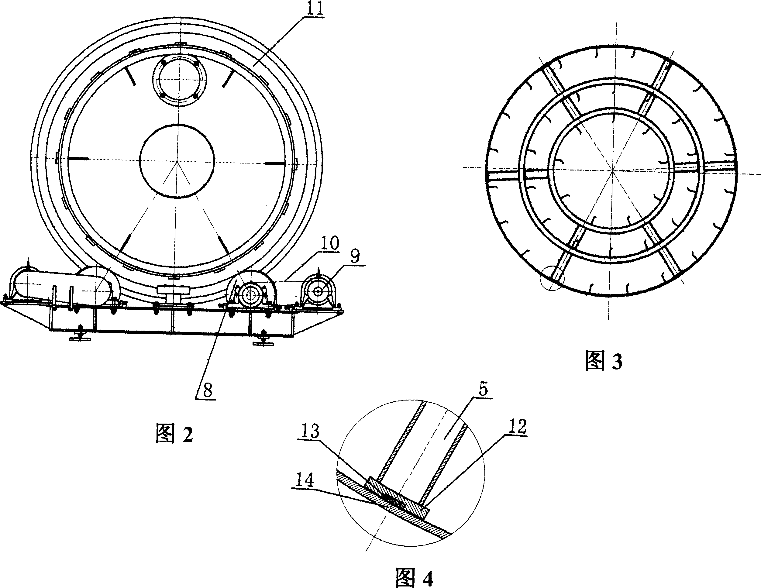
[0012] Such as figure 1 As shown in -4, the structure of the present invention is as follows: a multi-ring drum dryer 11 is composed of inner, middle and outer ring drums 4, 3, 2, and there are six supporting rods at both axial ends of each ring drum along the radial direction. Support, wherein one end is a fixed end support rod 1, and the other end is a movable end support rod 5,6. The two ends of the fixed end support rod 1 between the inner ring drum 4 and the middle ring drum 3 are respectively welded to the inner ring drum 4 and the middle ring drum 3, and the two ends of the fixed end support rod 1 between the middle ring drum 3 and the outer ring drum 2 are respectively Welded with middle ring drum 3 and outer ring drum 2. One end of the movable end support rod 6 between the inner ring drum 4 and the middle ring drum 3 is welded on the inner ring drum 4 , and the other end is provided with a chute 12 , which is slidingly matched with the slide block 13 welded on the i...


PUM


Abstract

The invention relates to a connection device of multi-ring roller drier, which comprises a roller formed by the inner, middle and outer multi-ring rollers. Said roller comprises a material inlet and a material outlet; two ends of each ring of roller comprise radial supports. he invention is characterized in that: the radial support at one end uses fixing welding, and another end uses axial slide block support. The invention has the advantages that: each ring of roller can attain radial support; the torsion deformation generated by inertia force in the rotation of roller is balanced to avoid large torsion deformation at the movable end of roller; and since the heat deformation generated by the temperature difference between rollers can be released, the damage caused by heat stress on the connection point between rollers can be prevented.

Description

technical field [0001] The invention belongs to a connection structure between the drums of a multi-ring drum dryer. Background technique [0002] The multi-ring drum dryer is different from the commonly used single drum dryer. It is a new type of high-efficiency and energy-saving dryer that has been used in recent years. Its working principle is as follows: Figure 1 Shown: a set of multiple ring-shaped rollers, each ring-shaped roller is evenly distributed along the periphery with multiple support rods at both ends, so that the multiple rollers form a concentric ring. The two ends of the outer cylinder 2 are fixedly connected to the rolling ring 7 respectively, and the two sets of supporting wheels 8 support the rolling ring 7 . Driven by the drag force, through gear-ring gear transmission or friction transmission, the whole cylinder rotates concentrically under the support and transmission of the support wheel 6 . The hot air and wet material enter the inner cylinder 4 f...

Claims


Application Information

Patent Timeline
Patent Type & Authority Applications(China)
IPC IPC(8): F26B11/04F26B3/08
Inventor 卢英林
Owner 卢英林
Why Eureka
Try Eureka