Massage machine

A massager and heater technology, which is applied in the direction of kneading massage apparatus, roller massage, massage auxiliary products, etc., to achieve the effect of improving heating or cooling effect

Inactive Publication Date: 2006-08-02
SANYO ELECTRIC CO LTD
View PDF1 Cites 12 Cited by
  • Summary
  • Abstract
  • Description
  • Claims
  • Application Information

AI Technical Summary

Problems solved by technology

[0005] In addition, when the temperature is low in winter, when the massager is placed on the affected area, it will feel cold and there will be an unpleasant feeling.

Method used


Image

  • Massage machine
  • Massage machine
  • Massage machine

Examples


Embodiment Construction

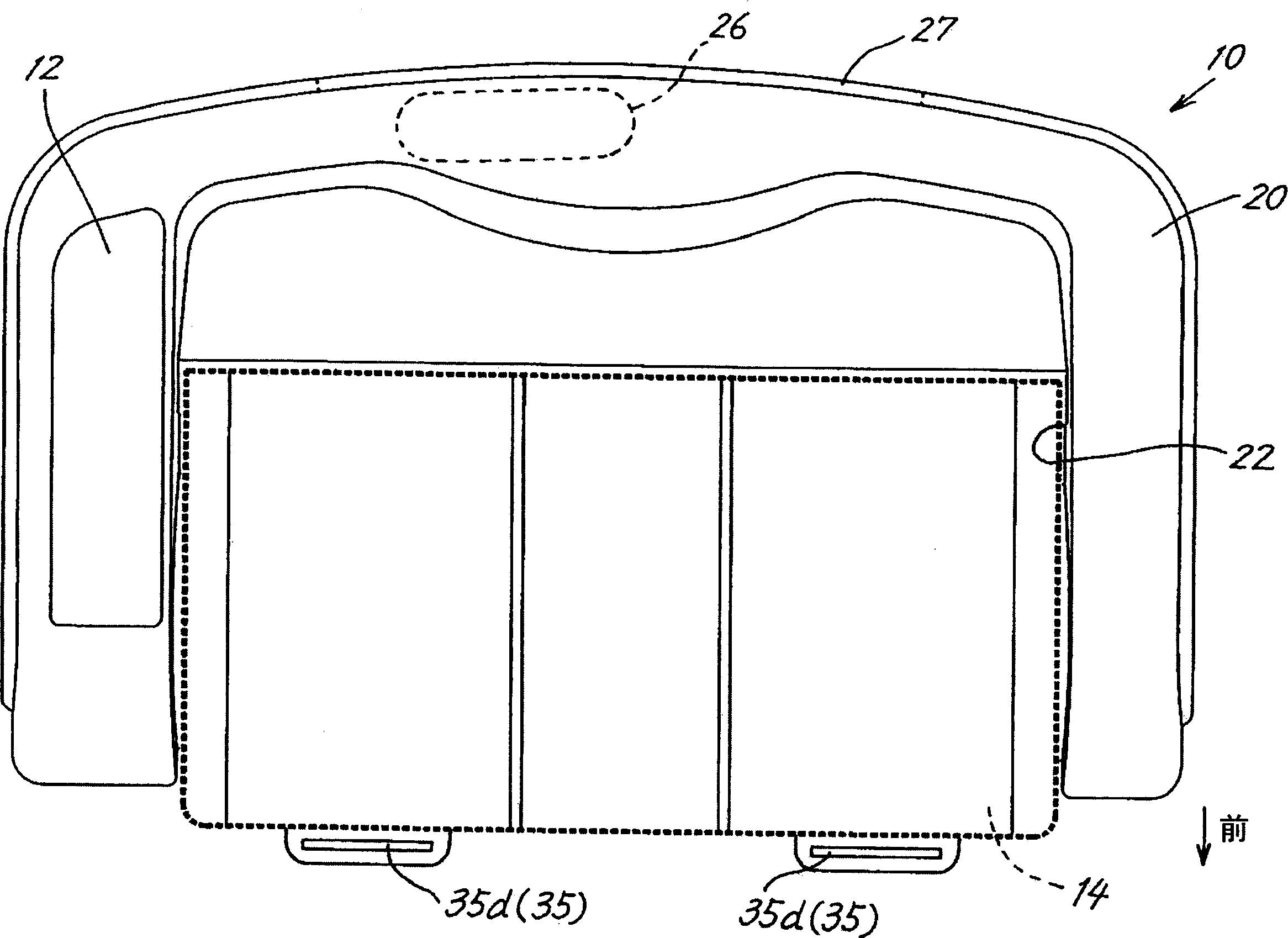
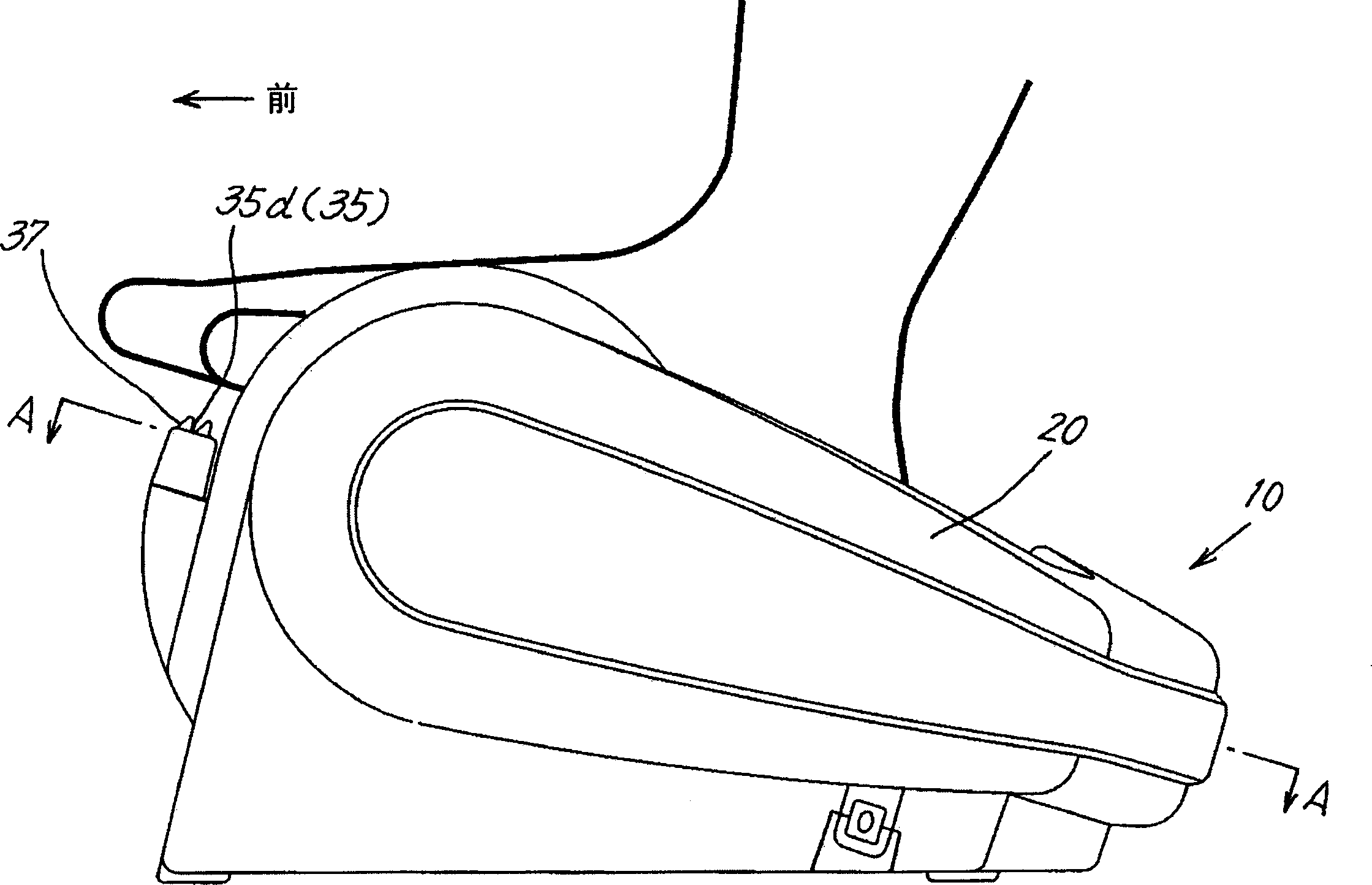
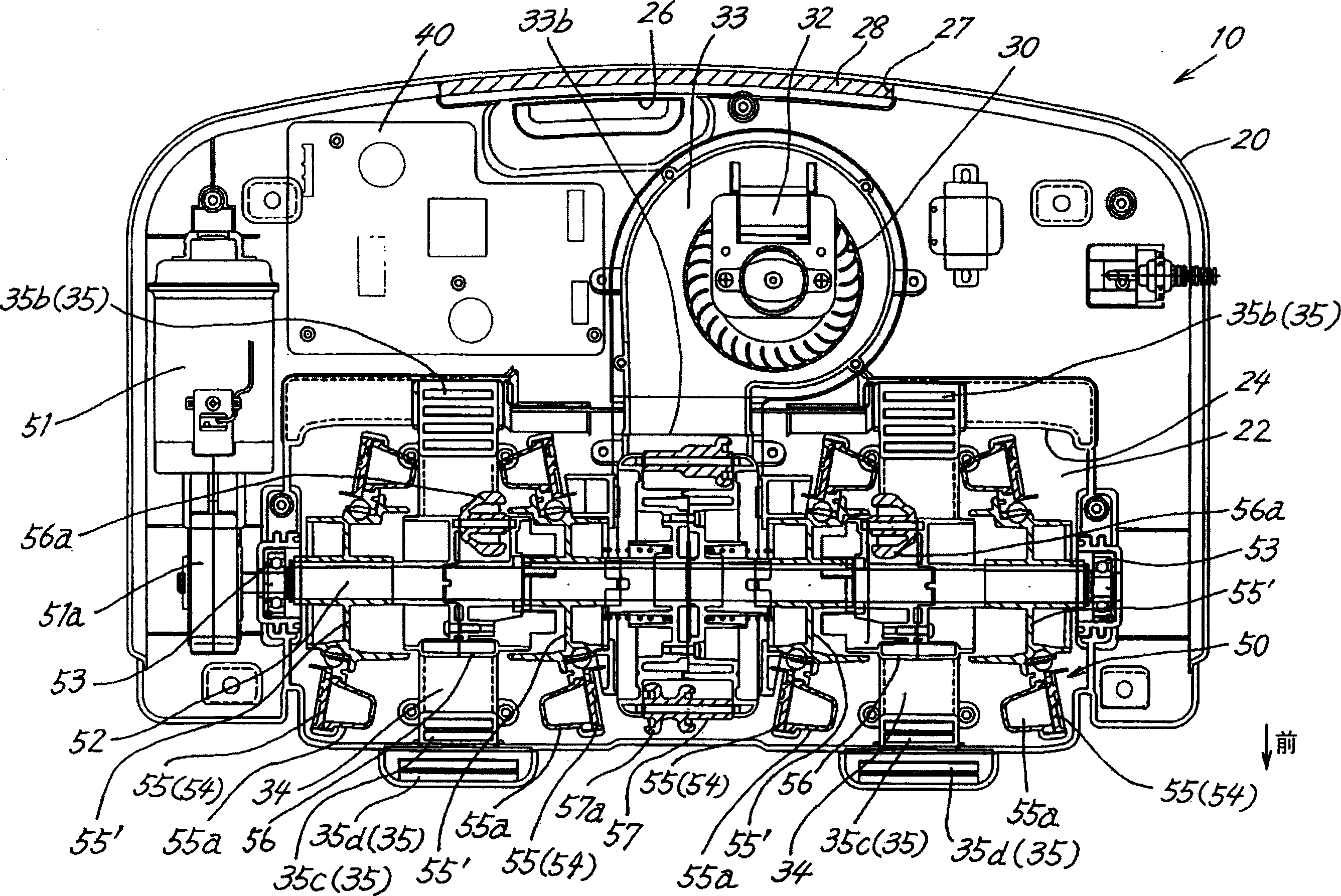
[0029] In the present invention Figure 1 to Figure 3 In the massager 10 shown, there is the following purpose, that is, to prevent the affected part from being stuffy and cold by blowing air to the affected part or near the affected part or using the heater 60 to provide heated warm air; For the structure of the device 10, refer to the best mode shown below, but the content disclosed in the description of the present invention is not limited thereto.

[0030] In addition, as the affected area, the foot end (the lower side of the ankle) massaged by the massager 10 is exemplified, but a massager for massaging the calf, thigh, arm, waist, back, shoulder, neck, etc. may also be used. applicable to the present invention.

[0031] figure 1 It is a top view of massager 10 of the present invention,

[0032] figure 2 It is a left side view of the massager 10 in a state where it is placed on the feet of the person being treated. In addition, in the following, for the sake of simp...


PUM


Abstract

A massager is provided. Through the massage mechanism (50) contained in the shell (20), in the massager that massages the affected part of the person being treated, in the inside of the shell (20), there is a fan (30) that blows air and drives the fan ( The motor (32) for the fan of 30) and the flow path (34) that guides the air sent by the fan (30) to the affected part of the person to be treated. The massager of the present invention heats or cools the feet of the treated person with warm air or blowing air, thereby improving the massage effect and providing comfortable massage.

Description

technical field [0001] The present invention relates to a massager suitable for massaging the affected part such as the foot of the person to be treated. More specifically, it provides a massager which can not only massage the affected part, but also cool or warm the affected part, thereby further Improve massage effect and massage comfortably. Background technique [0002] Such a massager has been provided, which can make a pair of rotating disc-shaped treatment bodies approach and leave, and rub and press the affected part of the treated person, specifically the end of the foot and the sole of the foot (such as Refer to Patent Document 1). [0003] Patent Document 1: JP-A-2001-204781 [0004] When the affected area is massaged, the blood circulation of the affected area will be accelerated, and the temperature of the affected area will rise. Therefore, with the generation of stuffy feeling, there will be a kind of unpleasant feeling. [0005] In addition, when the temp...

Claims


Application Information

Patent Timeline
Patent Type & Authority Applications(China)
IPC IPC(8): A61H7/00A61H15/02
Inventor 中村尚高桥伸明齐藤亮介高马一丰森田芳年
Owner SANYO ELECTRIC CO LTD
Why Eureka
Try Eureka