Instrument exchanging decice

A tool exchange and tool technology, which is applied in positioning devices, manufacturing tools, transportation and packaging, etc., can solve the problems of applying impact load, loosening pin wear and loosening time, and increasing impact load, etc.

Active Publication Date: 2006-08-02
BROTHER KOGYO KK
View PDF1 Cites 2 Cited by
  • Summary
  • Abstract
  • Description
  • Claims
  • Application Information

AI Technical Summary

Problems solved by technology

[0005] In the above conventional configuration, a collision load is applied when the tool is released, that is, when the release lever collides with the release pin.
Especially when the operating speed is increased to speed up the opening of the tool, the impact load will incre

Method used


Image

  • Instrument exchanging decice
  • Instrument exchanging decice
  • Instrument exchanging decice

Examples


Embodiment Construction

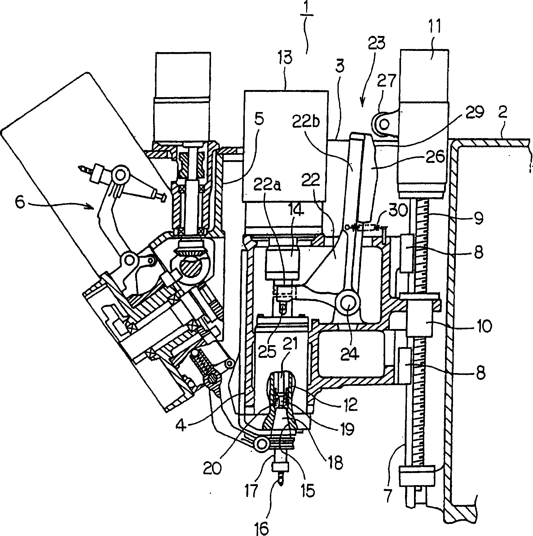
[0015] Refer below Figure 1 ~ Figure 3 The first embodiment of the present invention will be described. first, figure 1 It is a longitudinal sectional view showing a schematic structure of a machine tool to which this embodiment is applied. Such as figure 1 As shown, the machine tool 1 has: a column 2 erected on the base platform (not shown); a frame 3 composed of a box-shaped hollow shell horizontally arranged and fixed on the front surface of the column 2; The main shaft head 4 arranged in the frame 3 ; the rotatable indexing tool box 6 arranged on the frame 3 through the box supporting seat 5 .

[0016] A guide rail 7 is arranged vertically on the column 2 , and a spindle head 4 is provided on the guide rail 7 so as to be able to move up and down (Z-axis) freely via slide blocks 8 , 8 . A rotatable ball screw 9 is provided parallel to the guide rail 7 on the column 2 , and the ball screw 9 is screwed into and passed through a nut 10 fixed on the back of the spindle hea...


PUM


Abstract

A tool exchanger is arranged on a main spindle head base (4) and comprises an unclamping operation member (22), which releases a tool (16) installed in a main spindle (12) by abutting against an unclamping member (25) so as to press it. An unclamping cam (26) is arranged on the unclamping operation member (22) or a fixed section, and an action part (27) is arranged on the fixed section and the unclamping operation member (22) by being in contact with a cam surface (29) of the unclamping cam (26) to operate the unclamping operation member (22). In addition, an average moving speed of the unclamping operation member (22) for a movement towards the unclamping member (25) until abutting the unclamping member (25) is set as (V1). An average moving speed of the unclamping operation member (22) for the unclamping operation member (22) being abutting on the unclamping member (25) is set as (V2). The cam surface (29a) is shaped so that (V1) is more than (V2).

Description

(1) Technical field [0001] The present invention relates to a tool changer having a function of holding or releasing a tool of a machine tool on a spindle. (2) Background technology [0002] As an example of such a tool exchange device, there is a device disclosed in Japanese Patent Application Laid-Open No. 11-33805 (hereinafter referred to as Patent Document 1). In this device, a rotatable release lever (release operation member) is provided on the spindle head rotatably supporting the spindle. When the release lever rotates, the release lever collides with the release pin (release member) to Push it to open the tool mounted on the spindle. [0003] The rotation mechanism that rotates the release lever includes a release cam provided at a fixed portion and a roller (acting portion) rotatably provided on the release lever. The roller rotates the release lever by contacting the cam surface of the release cam. [0004] In the above configuration, when the spindle head is r...

Claims


Application Information

Patent Timeline
IPC IPC(8): B23Q3/157B23B31/24
CPCA61L2/232B32B27/18B62B5/06
Inventor 野村裕昭
Owner BROTHER KOGYO KK
Why Eureka
Try Eureka