
Pilot operated axial flow valve

An axial flow valve and pilot-operated technology, which is applied in the direction of valve lift, valve details, valve device, etc., can solve problems such as difficulty in the application of various actuators, inflexible coordination of actuators, and complex structure of axial flow valves. Simple, small drag coefficient and low cost

Inactive Publication Date: 2006-08-02
北京市燕山工业燃气设备有限公司 +1
View PDF0 Cites 2 Cited by
  • Summary
  • Abstract
  • Description
  • Claims
  • Application Information

AI Technical Summary

Problems solved by technology

[0003] The purpose of the present invention is to provide a pilot-operated axial flow valve, which solves the technical problems that the existing axial flow valve has complex structure, high cost, inflexible cooperation with actuators, and difficult application with various actuators.

Method used


Image

  • Pilot operated axial flow valve
  • Pilot operated axial flow valve
  • Pilot operated axial flow valve

Examples


Embodiment Construction

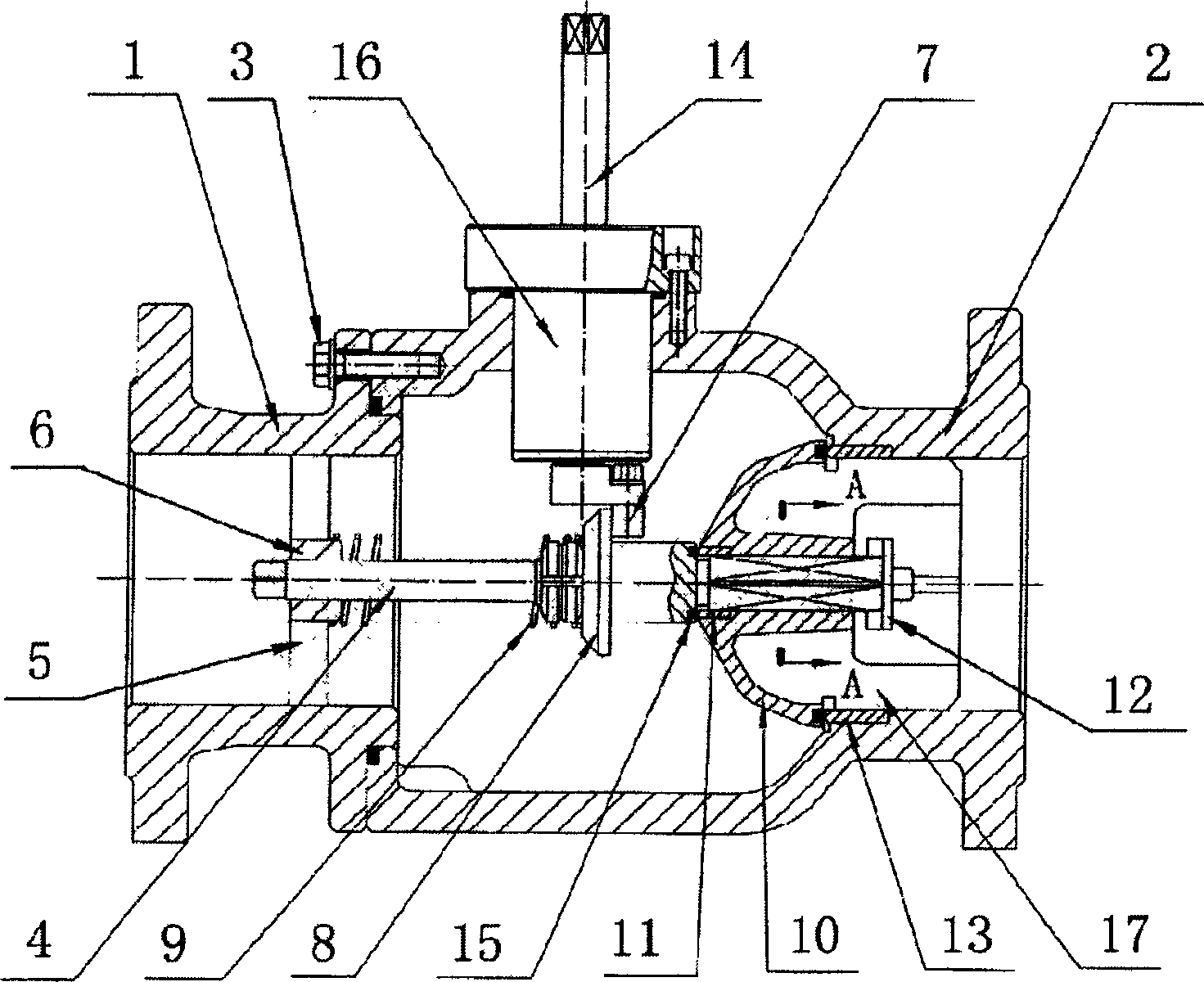
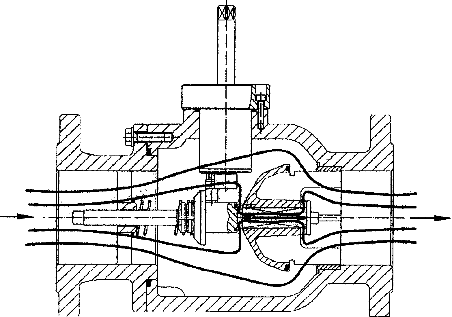
[0026] see figure 1 , the movement of the fluid flows along the direction of the common axis from the valve inlet to the valve outlet. The two outer streamlines farther from the axis indicate that the fluid flows out from the main valve seat, and the inner two streamlines closer to the axis indicate that the fluid flows from the pilot valve. Seat outflow. When the main valve disc is in the closed state, there is pressure fluid in the valve body, and the pressure acts on the main valve disc to make the opening force of the valve disc great. Therefore, when the valve stem is pulled to the left, the pilot valve disc will act first, and the pilot valve disc will move first. The action area is relatively small, so it is easy to pull, and the fluid flows downstream through the opened pilot valve disc. In this way, the pressure difference at both ends of the main valve disc can be reduced, and the main valve disc will also be opened if the valve stem is continued to be pulled.

[00...


PUM


Abstract

The pilot operated axial flow valve has a valve body comprising a small half valve body in the inlet end and a large half valve body in the outlet end screw connected; a valve rod through the guide hole in the inside cavity of the small half valve body; a catch plate connected to the middle section of the valve rod and matched with eccentric shaft, a repositioning spring between the catch plate and the guide hole; the eccentric shaft below the main shaft, the eccentric main shaft with axis perpendicular to that of the valve body; a main valve seat inside a through hole of the large half valve body and coaxial with the valve body; and a pilot operated valve with seat in the axis of the main valve clack and clack embedded to the reduced end of the valve rod. The pilot operated axial flow valve has simple structure, small resistance coefficient, great flow capacity and wide application.

Description

(1) Technical field [0001] The invention relates to a valve for controlling fluid movement, in particular to a gas regulating valve. (2) Background technology [0002] Existing radial flow valves generally include a valve body, a valve seat and a valve disc that cooperate with each other, and a valve stem located at the center of the shaft. When the fluid in the valve flows through the valve seat, the flow direction of the fluid is perpendicular to the axis of the valve body, and the medium passes through two turns from the inlet to the outlet. Therefore, the flow resistance is relatively large and the flow capacity is small. The existing axial flow valve adopts the design of the balanced valve core, which has a relatively complicated structure and high cost, and the actuator is integrated with the valve body, so it is not easy to cooperate with various actuators. (3) Contents of the invention [0003] The purpose of the present invention is to provide a pilot-operated ax...

Claims


Application Information

Patent Timeline
Patent Type & Authority Applications(China)
IPC IPC(8): F16K1/00F16K39/02F16K31/44
Inventor 齐旭
Owner 北京市燕山工业燃气设备有限公司
Learn More