Supercharge Your Innovation With Domain-Expert AI Agents!

Housing cage for holding built-in modules

A cage, built-in technology, applied in the direction of rack/frame structure, chassis/cabinet/drawer parts, instruments, etc., can solve problems such as unreasonable

Inactive Publication Date: 2006-08-02
FUJITSU SIEMENS COMP GMBH
View PDF0 Cites 0 Cited by
  • Summary
  • Abstract
  • Description
  • Claims
  • Application Information

AI Technical Summary

Problems solved by technology

[0005] The outlay for receiving built-in modules of different construction heights during the manufacture of the housing and receiving the built-in modules, as well as the costs for the necessary add-ons, is less significant since the receiving of built-in modules of the full height is rare Reasonable

Method used


Image

  • Housing cage for holding built-in modules
  • Housing cage for holding built-in modules
  • Housing cage for holding built-in modules

Examples


Embodiment Construction

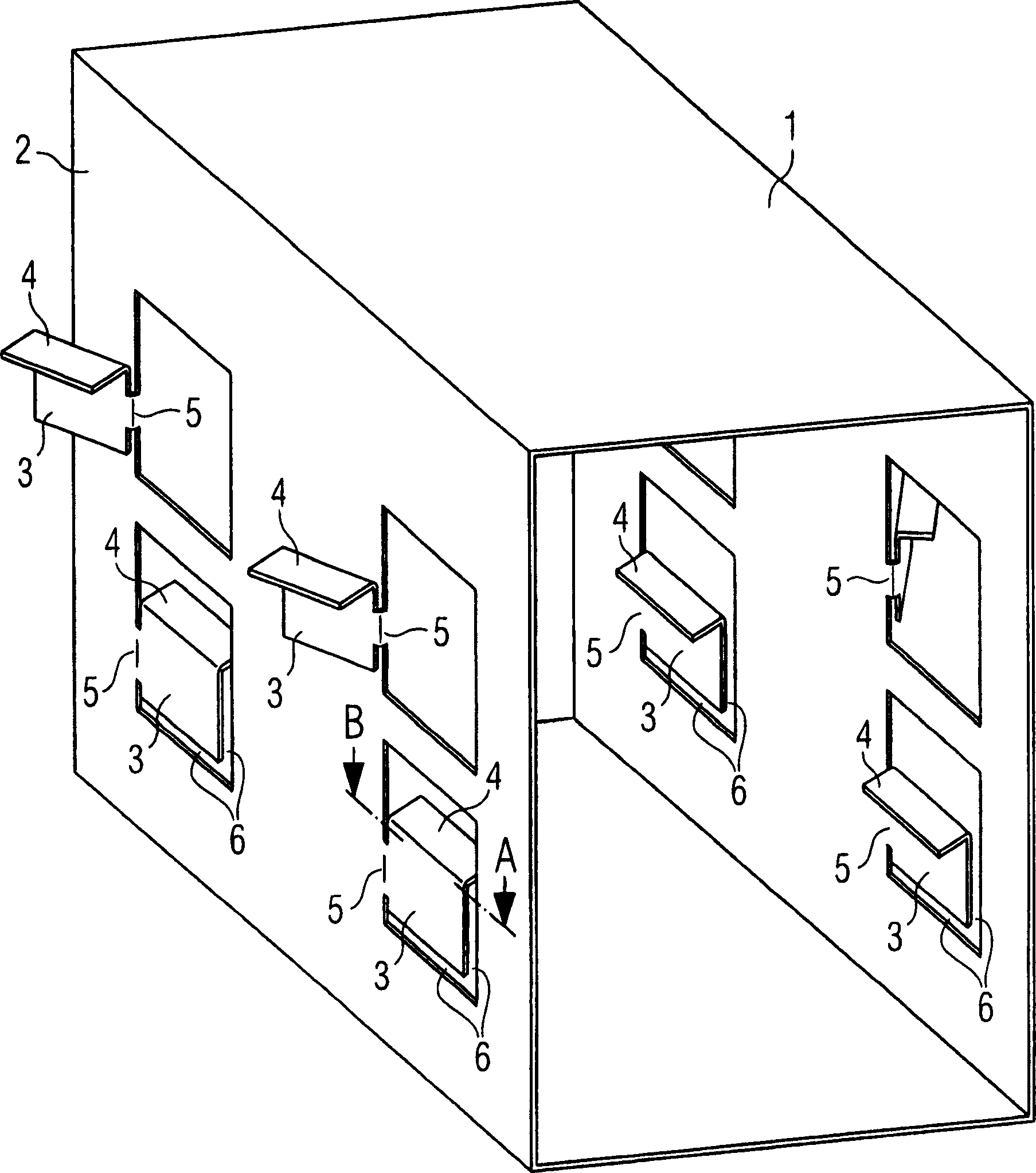
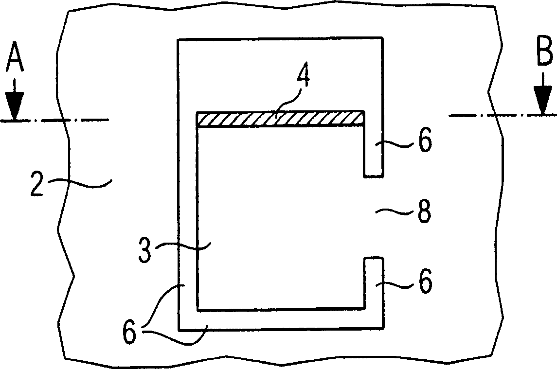
[0016] figure 1 A housing-type cage 1 is shown, the walls 2 of which each have four bendable wall sections 3 . The bendable wall section 3 is connected at an angle to the support surface 4 . In addition, the flexible wall section 3 is connected to one of the walls 2 of the housing-type cage 1 at a first leg 5 . Cut-outs 6 are provided between the other sides of the wall section 3 and the wall 2 of the housing-type cage.

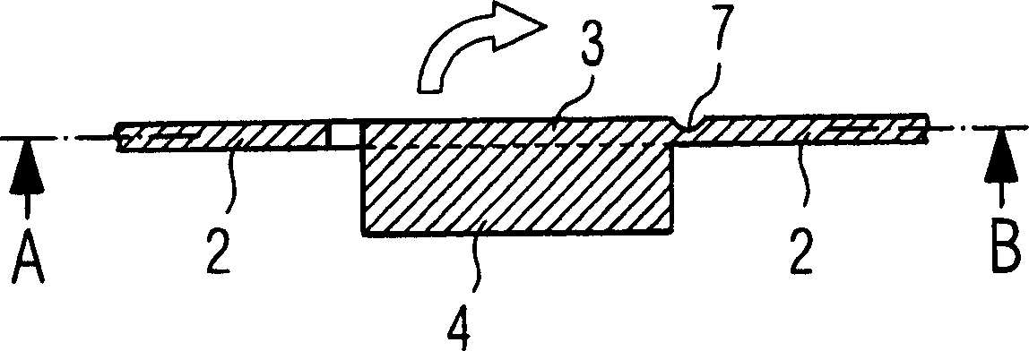
[0017] figure 2 A detailed plan view of the first embodiment of the wall section 3 along section A-B is shown. Here, the wall section 3 is offset from the wall 2 of the shell-type cage 1 with the contact surface 4 connected thereto via a groove 7 . If a built-in module is to be received in this shell-type cage 1, this built-in module requires that the support surface 4 is removed from the inside of the shell-type cage 1, so that the wall section 3 and the supporting frame connected thereto face 4 in figure 2 The direction of the arrow is bent from the...


PUM


Abstract

The present invention provides a housing cage with wall sections (3) and mounting or placement surfaces (4) for supporting the installed modules received into the housing cage. The wall sections (3) are connected only at one face (5) with the wall (2) of the housing cage, and sections between other sides of the wall sections (3) and the wall of the housing cage are provided, so that the wall sections can be bent relative to the wall of the housing cage along the first face (5).

Description

technical field [0001] The invention relates to a housing-type cage having a wall section and a bearing surface connected at an angle to the wall section for supporting a built-in module received in the housing cage. Background technique [0002] Shell-type cages for receiving built-in modules are well known. Such housing-type cages are used, for example, to receive drive modules in the drive cage of a computer housing. Due to the wide variety of appliances to be received, at least one of the dimensions of the modules to be received is often not specified here. For example, a 5″ drive module is received in a housing-type cage with its full or half construction height. In this case, the built-in module with half the construction height is further expanded into a built-in module of the entire construction height, so the attached housing-type cage Usually, support surfaces are provided for receiving built-in modules with half the overall height. [0003] However, in order t...

Claims


Application Information

Patent Timeline
Patent Type & Authority Applications(China)
IPC IPC(8): H05K7/18H05K5/02G06F1/16
CPCG11B33/128G06F1/181G06F1/183
Inventor F·克勒M·贝茨A·谢勒
Owner FUJITSU SIEMENS COMP GMBH
Features
  • R&D
  • Intellectual Property
  • Life Sciences
  • Materials
  • Tech Scout
  • Unparalleled Data Quality
  • Higher Quality Content
  • 60% Fewer Hallucinations
Learn More