Positioning apparatus and method of controlling positioning apparatus

A technology for positioning equipment and controllers, which is applied in the field of chip mounters and controls the positioning equipment, can solve the problems of increased cost and complex structure of exposure equipment, and achieve the effect of cost reduction and simple structure

Inactive Publication Date: 2006-08-09
FUJITSU LTD
View PDF1 Cites 0 Cited by
  • Summary
  • Abstract
  • Description
  • Claims
  • Application Information

AI Technical Summary

Problems solved by technology

Exposure equipment is also forced to have a complex structure
One has to face the increased cost of manufacturing exposure equipment

Method used


Image

  • Positioning apparatus and method of controlling positioning apparatus
  • Positioning apparatus and method of controlling positioning apparatus
  • Positioning apparatus and method of controlling positioning apparatus

Examples


Embodiment Construction

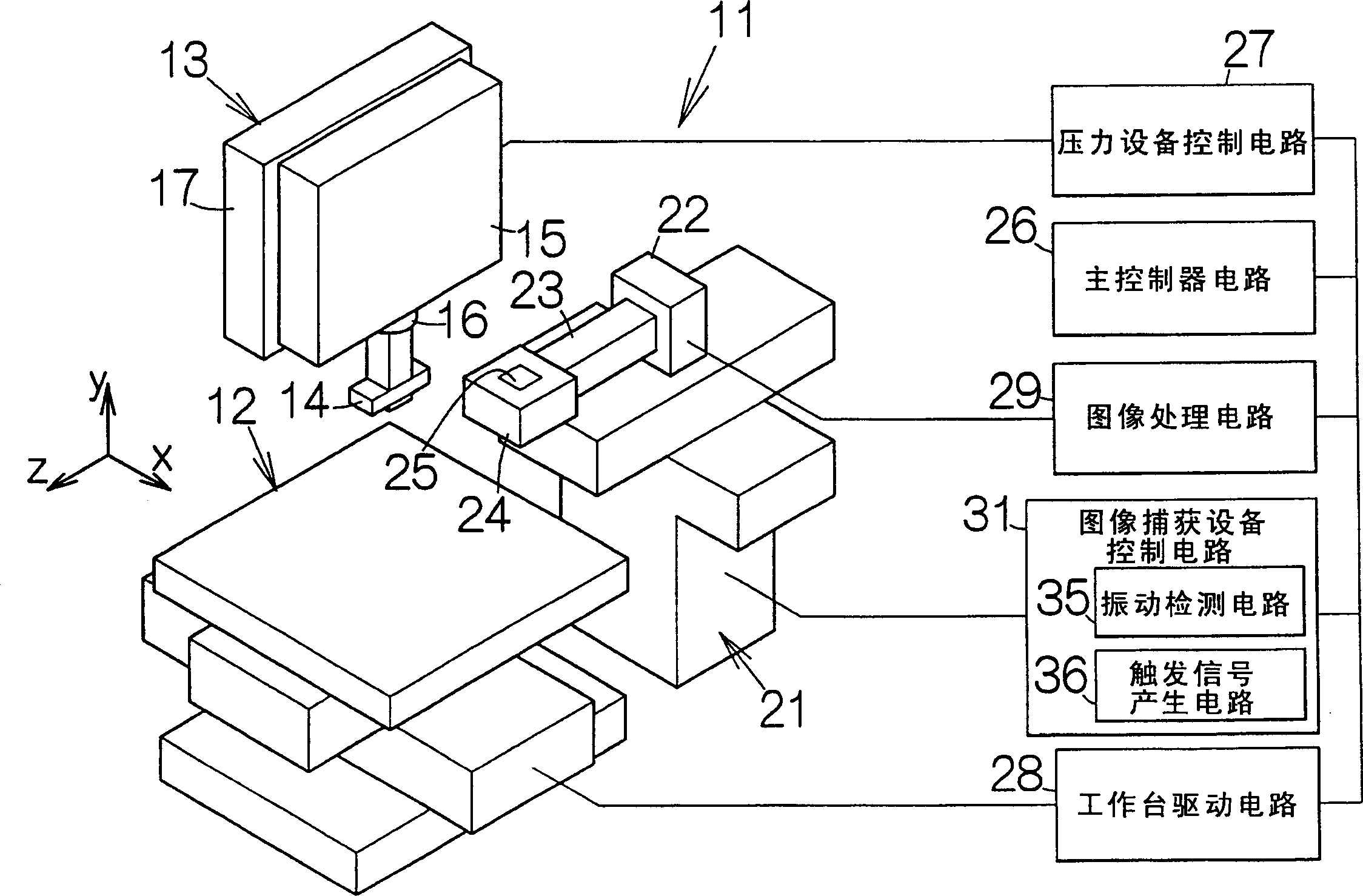
[0018] figure 1 A chip mounter 11 is schematically illustrated as an example of a processing device according to an embodiment of the present invention. The chip mounter 11 includes a table 12 defining an upper flat surface along a predetermined horizontal plane. The table 12 is allowed to move within this horizontal plane. The table 12 is designed to bear a printed circuit board on this upper flat surface.

[0019] Here, an xyz coordinate system is established in the chip mounter 11 . The y-axis of the xyz coordinate system extends in a direction perpendicular to the upper planar surface of the table 12 (ie, perpendicular to the horizontal plane). The table 12 is driven in the x-axis and y-axis directions. The position of table 12 can be identified by x-coordinates and y-coordinates.

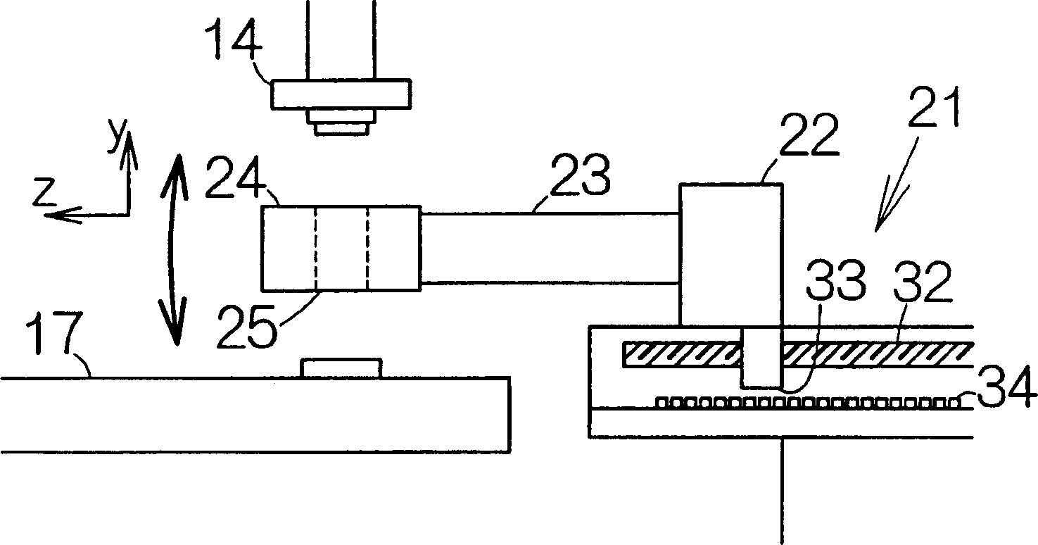
[0020] A pressure device 13 is associated with the table 12 . The pressure device 13 includes an ultrasound head 14 . The ultrasonic head 14 is designed to hold circuit component chips a...


PUM


Abstract

A movable member moves along a predetermined guide path. A supporting member extends from the movable member. A processing unit is fixed to the tip end of the supporting member. A sensor detects the movement of the movable member. When the movable member has stopped moving, the processing unit is subjected to a transient due to the inertia acting on the processing unit. The transient is detected based on the waveform of the sensor signal. The position of the processing unit can thus precisely be detected based on the sensor signal. The time for starting the operation of the processing unit can optimally be determined. The processing unit is thus allowed to start operating at the determined time. The processing unit is allowed to start operating in a shorter time after the movable member has stopped moving, even when the transient remains in the processing unit.

Description

technical field [0001] The present invention relates to positioning equipment contained in handling or processing equipment, such as chip mounters designed to mount electronic component chips onto printed circuit boards. The invention also relates to a method of controlling the positioning device. Background technique [0002] For example, as disclosed in Japanese Patent Application Laid-Open No. 2003-124112, exposure equipment is generally utilized in fine processing of wafers. Optical units, masks, etc. are aligned with the wafer placed on the stage in the exposure apparatus. For example, the stage moves in the horizontal direction to position the optical unit and mask. There is still a transition in the workbench after the workbench has stopped moving. The optical unit and mask are driven to move synchronously with the transition process. Optical units and masks can be aligned to the wafer without errors. Position deviation can be eliminated. Precise alignment is ob...

Claims


Application Information

Patent Timeline
Patent Type & Authority Applications(China)
IPC IPC(8): H01L21/00H01L21/68H01L21/027H01L21/50H05K13/04
CPCG05B19/402G05B2219/45026G05B2219/37388
Inventor 小林泰山高田英治须藤和巳
Owner FUJITSU LTD
Why Eureka
Try Eureka