
Method executed by user equipment and user equipment

A technology of user equipment and physical downlink, applied in the field of user equipment, can solve the problems of adding low-priority synchronization sources for UEs, failing to serve as UE synchronization sources, conflicts, etc.

Inactive Publication Date: 2020-10-09
SHARP KK +1
View PDF0 Cites 0 Cited by
  • Summary
  • Abstract
  • Description
  • Claims
  • Application Information

AI Technical Summary

Problems solved by technology

[0060] The UE IDs determined by different UEs (especially short IDs, such as physical layer IDs) may conflict, resulting in the inability to correctly identify the source and / or destination UE IDs at the physical layer
[0061] In GNSS-based SL synchronization, even if the base station has been synchronized to GNSS, it still cannot be used as the synchronization source of the UE, which greatly increases the probability that the UE selects a low-priority synchronization source or even fails to select a synchronization source

Method used


Image

  • Method executed by user equipment and user equipment
  • Method executed by user equipment and user equipment
  • Method executed by user equipment and user equipment

Examples


Embodiment 1

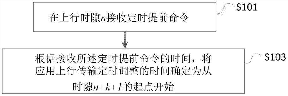
[0196] Below, combine figure 1 To illustrate the method executed by the user equipment in the first embodiment of the present invention.

[0197] figure 1 It is a flowchart showing the method executed by the user equipment according to the first embodiment of the present invention.

[0198] Such as figure 1 As shown, in the first embodiment of the present invention, the steps performed by the user equipment UE include: step S101 and step S103.

[0199] Specifically, in step S101, a timing advance command is received in the uplink time slot n. among them,

[0200] · The uplink time slot n may be the last time slot of the uplink time slot that overlaps with one or more time slots for PDSCH reception.

[0201] · The PDSCH may be a PDSCH that provides a timing advance command.

[0202] · When determining the uplink time slot n, it can be assumed that T TA =0, where T TA It is the value of uplink transmission timing adjustment, the unit is second.

[0203] · When determining the uplink t...

Embodiment 2

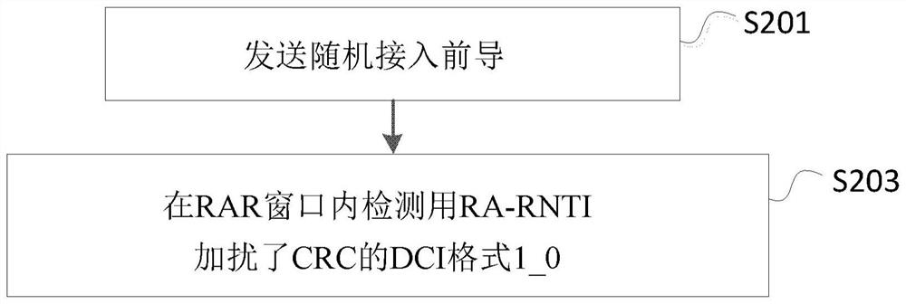
[0262] Below, combine figure 2 To illustrate the method executed by the user equipment in the second embodiment of the present invention.

[0263] figure 2 It is a flowchart showing the method executed by the user equipment according to the second embodiment of the present invention.

[0264] Such as figure 2 As shown, in the second embodiment of the present invention, the steps performed by the user equipment UE include: step S201 and step S203.

[0265] Specifically, in step S201, a random access preamble (random access preamble, sometimes referred to as physical random access channel, PRACH) is sent. Wherein, the transmission of the random access preamble can be triggered by a higher layer, can also be triggered by a PDCCH order (PDCCH order), or can be triggered by other methods.

[0266] In addition, in step S203, the DCI format 1_0 in which the CRC is scrambled with RA-RNTI is detected in the RAR (Random Access Response) window.

[0267] Optionally, if the UE detects the DCI f...

Embodiment 3

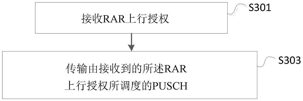
[0273] Below, combine image 3 To illustrate the method executed by the user equipment in the third embodiment of the present invention.

[0274] image 3 It is a flowchart showing the method executed by the user equipment according to the third embodiment of the present invention.

[0275] Such as image 3 As shown, in the third embodiment of the present invention, the steps performed by the user equipment UE include: step S301 and step S303.

[0276] Specifically, in step S301, the RAR uplink authorization is received. Wherein, the RAR uplink grant may be included in a MAC RAR, the MAC RAR may be included in a MAC PDU, and the MAC PDU may be carried by a PDSCH. In addition, sometimes, when the context is clear, it can also be considered that the PDSCH carries a "RAR message" (RAR message), and the RAR message contains the RAR uplink grant.

[0277] In addition, in step S303, the PUSCH scheduled by the received RAR uplink grant is transmitted. The UE may assume that the minimum tim...


PUM


Abstract

The invention provides a method executed by user equipment. The method comprises the following steps: receiving a timing advance command in an uplink time slot n; and according to the received timingadvance command, determining time of applying uplink transmission timing adjustment as starting from the starting point of the uplink time slot n + k + 1. K is further determined according to the duration of N1 symbols; the value of N1 corresponds to at least one of the following: PDSCH decoding time defined by a physical downlink shared channel PDSCH processing capability 1 when the processing capability assumption is satisfied is referenced, the maximum PDSCH decoding time defined by the PDSCH processing capability 1, the maximum PDSCH decoding time defined by the PDSCH processing capability1 when the extra PDSCH demodulates the reference signal DM-RS is configured, the minimum PDSCH decoding time defined by the PDSCH processing capacity 1 and the minimum PDSCH decoding time defined bythe PDSCH processing capacity 1 when the additional PDSCH DM-RS is configured; and n, k and N1 are integers respectively.

Description

Technical field [0001] The present invention relates to the field of wireless communication technology, and in particular to methods executed by user equipment and corresponding user equipment. Background technique [0002] In March 2016, at the RAN#71 plenary meeting of the 3rd Generation Partnership Project (3rd Generation Partnership Project: 3GPP), a new research project on 5G technical standards (see Non-Patent Document 1) was approved. The purpose of this research project is to develop a new wireless (New Radio: NR) access technology to meet all 5G application scenarios, requirements and deployment environments. NR mainly has three application scenarios: Enhanced Mobile Broadband (eMBB), Massive Machine Type Communication (mMTC), and Ultra-Reliable and Low Latency Communications (URLLC). In June 2017, at the RAN#75 plenary meeting of the 3rd Generation Partnership Project (3rd Generation Partnership Project: 3GPP), the corresponding 5G NR work project (see Non-Patent Docum...

Claims


Application Information

Patent Timeline
IPC IPC(8): H04W72/12H04W74/08H04L1/00H04L1/18H04L5/00
CPCH04W74/0833H04L1/0061H04L1/1812H04L5/0048H04L5/0055H04W72/23H04W56/0015H04W72/0446H04L27/26025H04L1/1864H04L1/1887H04W56/0045H04L5/0094H04L5/0051H04L5/0064H04W72/044H04W72/1273H04W74/008
Inventor 罗超刘仁茂
Owner SHARP KK
Learn More