Waveform generation identification method and computer readable medium

A recognition method and waveform generation technology, applied to computer parts, calculations, calculation models, etc., can solve the problems of IED time reduction sensors, etc.

Pending Publication Date: 2021-05-04
RICOH KK
View PDF1 Cites 0 Cited by
  • Summary
  • Abstract
  • Description
  • Claims
  • Application Information

AI Technical Summary

Problems solved by technology

[0006] However, according to the technology disclosed in Japanese Patent No. 3107020, in the case of implementing the equivalent current dipole method, there is a problem that it is not possible to determine the timing of the IED in an appropriate manner and reduce the sensor

Method used

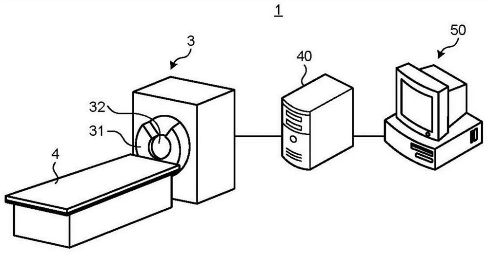
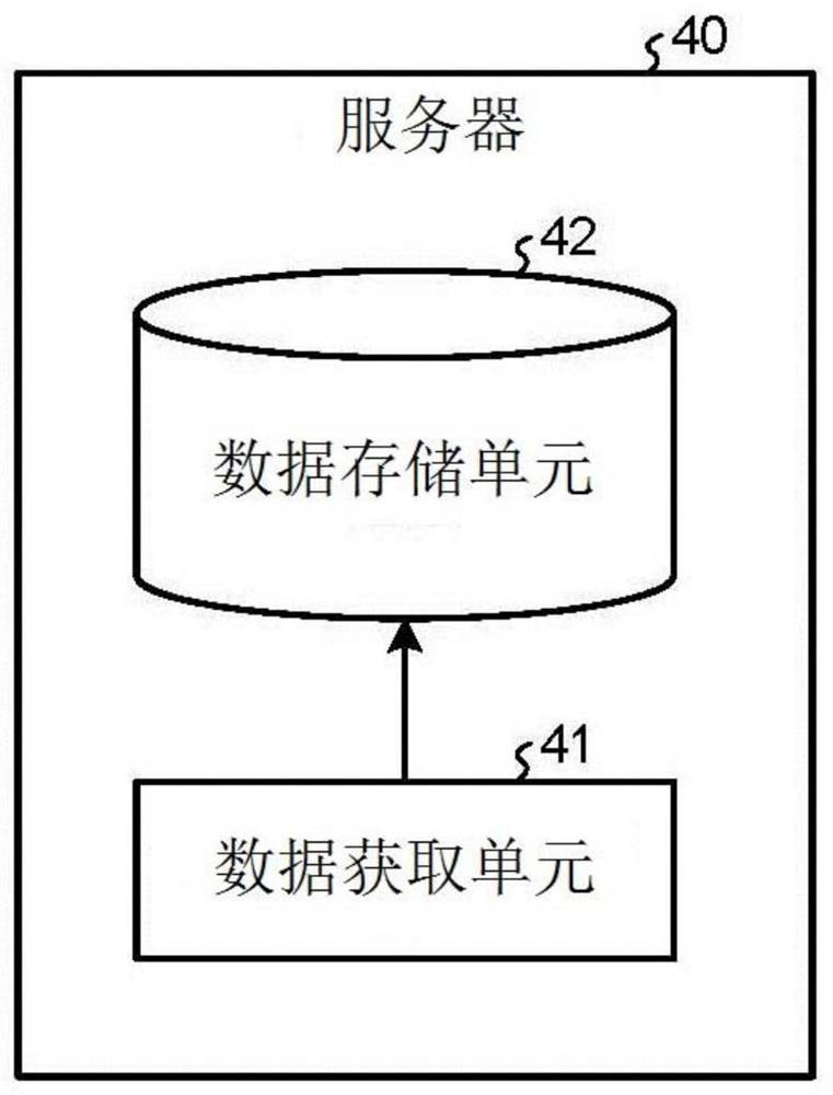
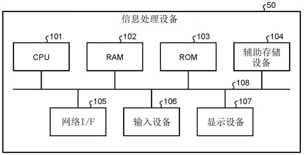

Image

  • Waveform generation identification method and computer readable medium
  • Waveform generation identification method and computer readable medium
  • Waveform generation identification method and computer readable medium

Examples


Embodiment Construction

[0023] The terms used herein are for describing specific embodiments only, not for limiting the present invention.

[0024] In this specification, unless the context clearly indicates otherwise, the singular forms "a", "an" and "a class" shall also include the plural forms.

[0025] In describing the preferred embodiments shown in the drawings, specific terminology may be employed for the sake of clarity of presentation. However, the technical specifications disclosed in this patent are not limited to the specific terms selected, and it should be understood that each specific element includes all technical equivalents that have the same function, operate in a similar manner, and achieve similar results.

[0026] Embodiments of the present invention will be described in detail below with reference to the accompanying drawings.

[0027] Exemplary embodiments of a waveform generation identification method and a computer-readable medium are described in detail below with referenc...


PUM


Abstract

A waveform generation identification method comprises the following steps: comparing single waveform data obtained by a plurality of sensors with at least one piece of characteristic waveform information; determining the occurrence probability of the characteristic waveform information in at least one part of the waveform data based on the relevancy between the peak part of the waveform data and the characteristic waveform information; and based on the occurrence probability, identifying the occurrence time of a part matched with the characteristic waveform information and a related sensor.

Description

technical field [0001] The invention relates to a waveform generation identification method and a computer-readable medium. Background technique [0002] Traditionally, in MEG or when analyzing MEG, analyzing its characteristic waveform is an extremely important factor. However, as technology advances, both the sampling frequency and the number of sensors used for measurement are increasing, leading to a tendency for the time required to visually search for waveforms to increase. [0003] For example, in the bedside diagnosis of epilepsy using magnetoencephalography, a method called the equivalent current dipole method is used to assess localization of epileptic foci. In the equivalent current dipole method, a current source (dipole) that produces a magnetic field measured on the scalp is estimated. For dipole estimation, from the time series of multiple sensors, it is necessary to narrow down the range to determine the time (start point) at which characteristic waveform i...

Claims


Application Information

Patent Timeline
Patent Type & Authority Applications(China)
IPC IPC(8): A61B5/00A61B5/245A61B5/372
CPCA61B5/4094A61B5/72A61B2576/026G06N20/00G01R23/005G06F2218/14G06F2218/06G06F2218/10G06F2218/12
Inventor 平野谅司平田雅之中田乙一
Owner RICOH KK
Why Eureka
Try Eureka