
Lifting mechanism of intelligent 3D printer forming platform

A technology of 3D printer and lifting mechanism, which is applied in the field of 3D printing and can solve problems such as affecting transmission, small size, and errors

Inactive Publication Date: 2020-10-23
和氏璧(广州)科技有限公司
View PDF8 Cites 0 Cited by
  • Summary
  • Abstract
  • Description
  • Claims
  • Application Information

AI Technical Summary

Problems solved by technology

[0004] Aiming at the deficiencies of the prior art, the present invention provides a lifting mechanism for the molding platform of an intelligent 3D printer, which solves the problem that most of the lifting mechanisms of the molding platform currently on the market use a motor connected to a single-side lead screw to drive the lifting movement of the platform. Although the structure of the lead screw is simple, when the lead screw is working, its transmission will be affected when it is subjected to lateral force, and the size of the lead screw is generally smaller than the size of the printed item, so when printing heavy items , the lead screw will deform and affect the transmission. In addition, when the existing forming platform returns to the initial state, its height often has a certain error. At this time, the height needs to be adjusted, and the existing adjustment method is by using It is time-consuming and labor-intensive to adjust several screws to make the forming platform touch the top of the screw, and because the screwing length is different when screwing the screws, the forming platform has a certain height difference at this time. There will be some errors in the products that come out, which will cause the problem of waste in production

Method used


Image

  • Lifting mechanism of intelligent 3D printer forming platform
  • Lifting mechanism of intelligent 3D printer forming platform
  • Lifting mechanism of intelligent 3D printer forming platform

Examples


Embodiment Construction

[0061] The following will clearly and completely describe the technical solutions in the embodiments of the present invention with reference to the accompanying drawings in the embodiments of the present invention. Obviously, the described embodiments are only some, not all, embodiments of the present invention. Based on the embodiments of the present invention, all other embodiments obtained by persons of ordinary skill in the art without making creative efforts belong to the protection scope of the present invention.

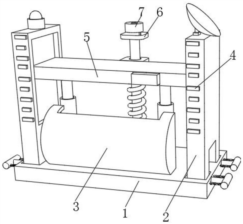
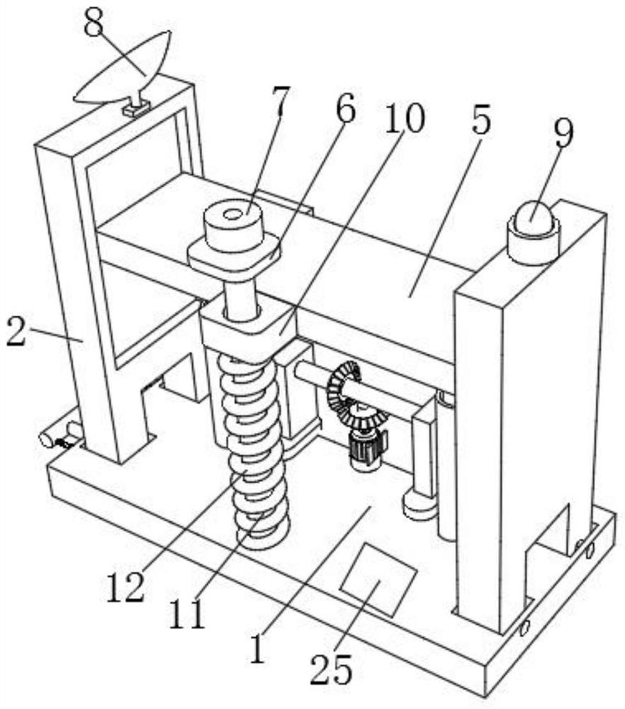
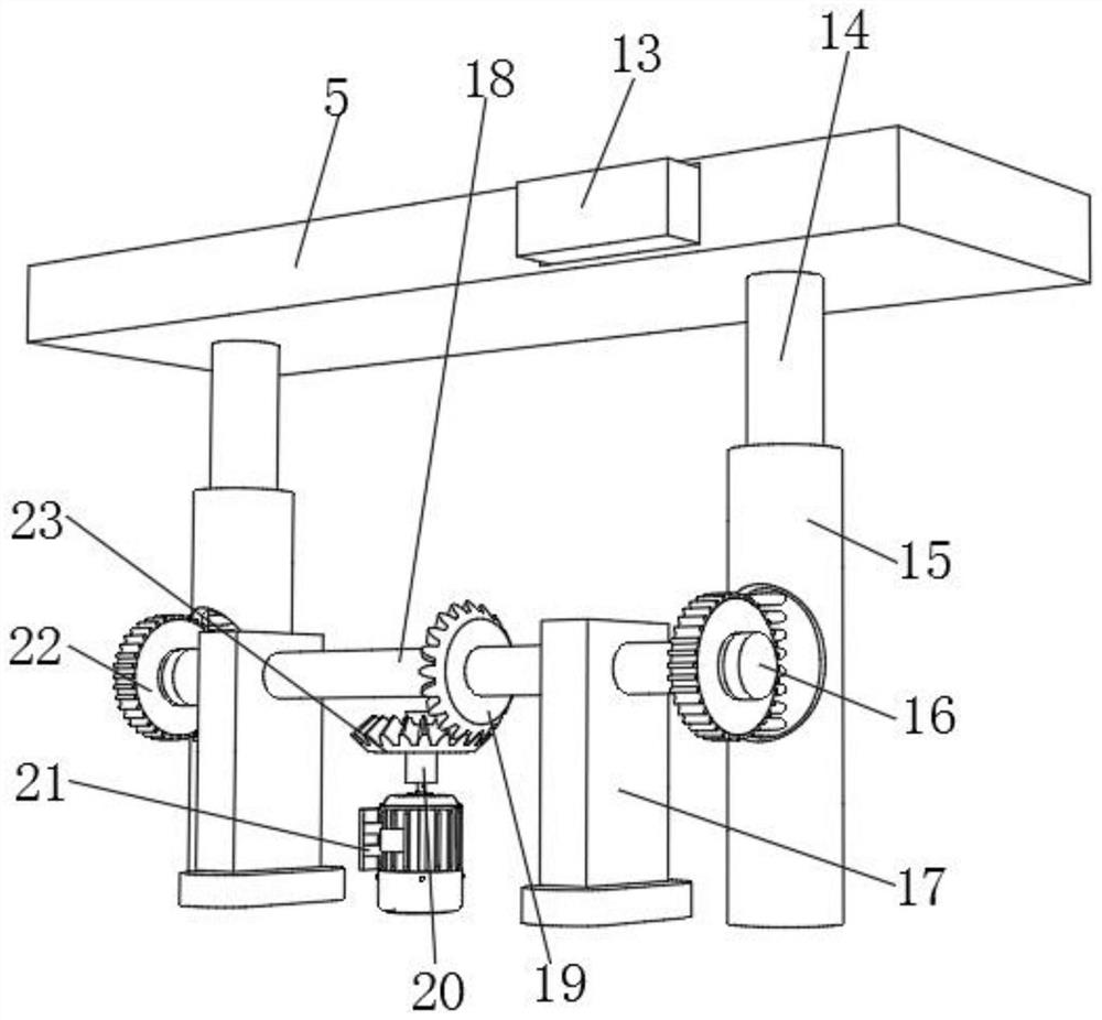
[0062] see Figure 1-5 , the present invention provides a technical solution: a lifting mechanism for an intelligent protective shell 3D printer forming platform, including a substrate 1, the upper surface of the substrate 1 is fixedly connected with the bottom ends of two sets of first support plates 2, and the upper surface of the substrate 1 A protective shell 3 is provided, the first support plate 2 is slidably connected with the forming platform 5, the ba...


PUM


Abstract

The invention relates to the technical field of 3D printing, and discloses a lifting mechanism of an intelligent 3D printer forming platform. The lifting mechanism comprises a base plate, wherein theupper surface of the base plate is fixedly connected with the bottom ends of two sets of first supporting plates; a protective shell is arranged on the upper surface of the base plate; the first supporting plates are in sliding connection with the forming platform; and the base plate is fixedly connected with the bottom end of a telescopic rod. According to the lifting mechanism of the intelligent3D printer forming platform, a connecting shaft is driven to rotate through an arranged motor, so that a second bevel gear and a first bevel gear are matched to rotate, then the first bevel gear drives a transverse shaft to rotate, the transverse shaft drives a limiting block to rotate, the limiting block drives a gear to rotate, then the gear is matched with a moving rod, so that the moving rodis lifted under the limiting of a fixing column; and a scale plate is arranged to be matched with the first supporting plates, so that the forming platform can be stably lifted, meanwhile, the formingplatform is guaranteed to be in a horizontal state, and the height difference is prevented.

Description

technical field [0001] The invention relates to the technical field of 3D printing, in particular to a lifting mechanism for a forming platform of an intelligent 3D printer. Background technique [0002] 3D printer, also known as three-dimensional printer, is a machine of rapid prototyping technology. It is a technology based on digital model files and using bondable materials such as powdered metal or plastic to construct objects by layer-by-layer printing. It is a cumulative manufacturing technology that creates three-dimensional objects by printing layers of adhesive materials. The basic principle is that by putting data and raw materials into the 3D printer, the machine will build the product layer by layer according to the program, and The product is printed out and ready for immediate use. At present, most of the lifting mechanisms of the forming platform in the market use a motor connected to a single-side screw to drive the lifting movement of the platform. Although...

Claims


Application Information

Patent Timeline
IPC IPC(8): B29C64/232B29C64/393B29C64/245B33Y30/00B33Y50/02
CPCB33Y30/00B33Y50/02B29C64/232B29C64/245B29C64/393
Inventor 黄耿权
Owner 和氏璧(广州)科技有限公司
Learn More