Coherence factor adaptive ultrasound imaging

A coherence factor, ultrasonic imaging technology, applied in ultrasonic/sonic/infrasonic diagnosis, application, material analysis using sonic/ultrasonic/infrasonic waves, etc.

Inactive Publication Date: 2006-08-16
SIEMENS MEDICAL SOLUTIONS USA INC
View PDF5 Cites 8 Cited by
  • Summary
  • Abstract
  • Description
  • Claims
  • Application Information

AI Technical Summary

Problems solved by technology

However, due to weak or non-existent transmit focusing, clutter levels are generally higher than conventional imaging using a focused transmit beam

Method used


Image

  • Coherence factor adaptive ultrasound imaging
  • Coherence factor adaptive ultrasound imaging

Examples


Embodiment Construction

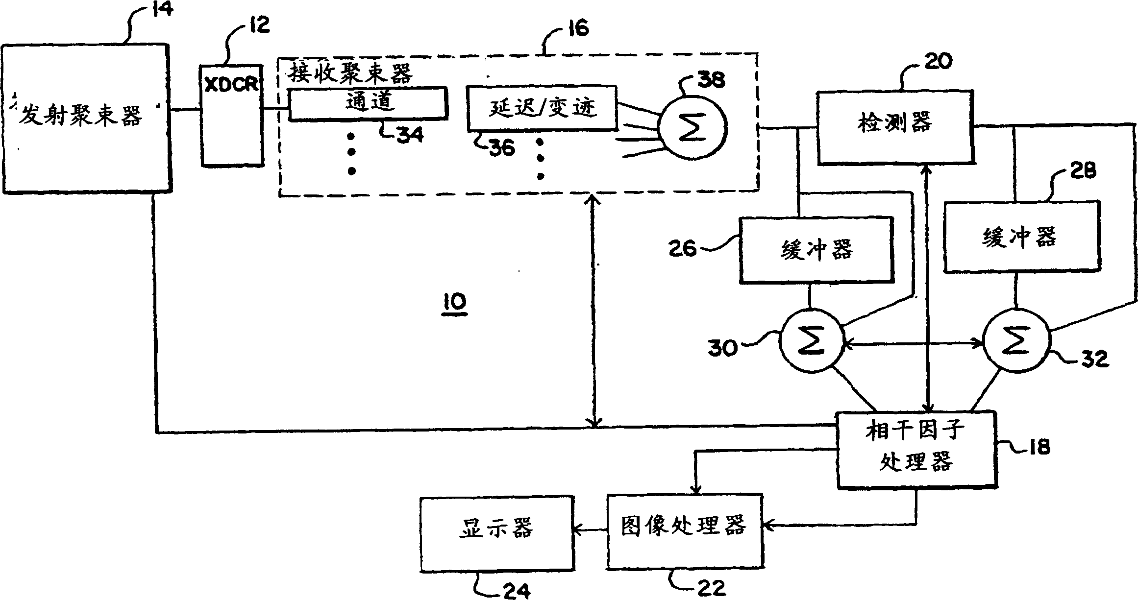
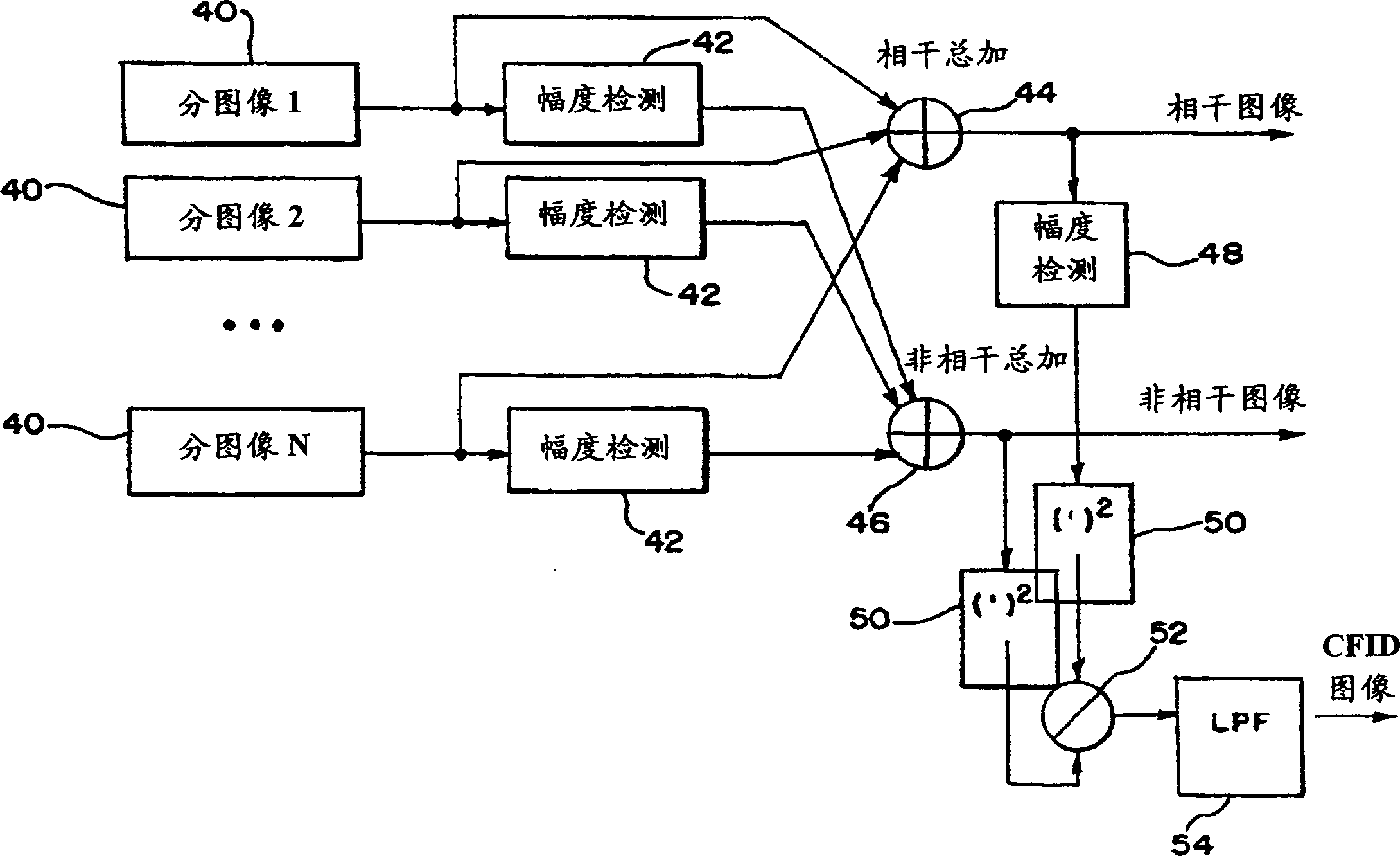
[0013] Acquire a set of NxM signals from the object, where N is the number of array elements and M corresponds to changes in data acquisition and / or processing parameters. These parameters include transmit aperture function, transmit waveform, receive aperture function and receive filter function in space and time. The coherence factor is calculated as the ratio of the energy summed coherently to the energy summed at least partially incoherently of these signals. In one embodiment, the coherence factor image is calculated in the image domain as a function of the coherent and incoherent summation of the partial images formed with different parameters. At least one parameter is modified as a function of the coherence factor. In one embodiment, the coherence factor is used to modulate the grayscale or color of the image synthesized from the partial images.

[0014] figure 1 One embodiment for an adaptive ultrasound imaging system 10 is shown. System 10 is an ultrasound imagin...


PUM


Abstract

A set of NxM signals are acquired from an object, where N is the number of array elements and M corresponds to variations in data acquisition and / or processing parameters. The parameters include transmit aperture functions, transmit waveforms, receive aperture functions, and receive filtering functions in space and / or time. A coherence factor is computed as a ratio of the energy of the coherent sum to the energy of the at-least-partially incoherent sum of channel or image signals acquired with at least one different parameter. Partial beamformed data may be used for channel coherence calculation. For image domain coherence, a component image is formed for each different transmit beam or receive aperture function, and a coherence factor image is computed using the set of component images. The coherence factor image is displayed or used to modify or blend other images formed of the same region.

Description

technical field [0001] The present invention relates to adaptive ultrasound imaging as a function of coherence. Specifically, imaging is performed as a function of the coherence of the acquired data. Background technique [0002] The lack of coherence can be limited by aberration correction and array alignment. Aberration correction is affected by various issues such as lack of suitable point targets, aberrations are propagation path dependent and change over time due to tissue and transducer movement, and estimation and correction require fine spatial sampling and high computation cost. Array calibration is less commonly used in practice due to the complexity of the software and system-probe combination. [0003] Clutter can be suppressed using a coherence factor. For example, US Patent No. _____ (Application Serial No. 10 / 814,959, filed March 31, 2004) discloses the use of a coherence measure (the disclosure of which is incorporated herein by reference). A coherence f...

Claims


Application Information

Patent Timeline
Patent Type & Authority Applications(China)
IPC IPC(8): A61B8/00G01N29/00G03B42/06G01S15/89
CPCG01S7/52046G01S15/8993A61B8/00
Inventor D·-L·D·刘C·E·布拉德利L·J·托马斯J·C·拉津比K·F·乌斯图纳
Owner SIEMENS MEDICAL SOLUTIONS USA INC
Why Eureka
Try Eureka