
Super plasticity extruding and forming device for micro parts

A technology of extrusion forming and superplasticity, which is applied in the direction of stamping machines, presses, manufacturing tools, etc., can solve the problems of small extrusion strokes, achieve uniform extrusion speed, precisely control extrusion precision, and improve quality

Inactive Publication Date: 2006-08-23
NORTHWESTERN POLYTECHNICAL UNIV
View PDF1 Cites 12 Cited by
  • Summary
  • Abstract
  • Description
  • Claims
  • Application Information

AI Technical Summary

Problems solved by technology

Due to the influence of its forming principle, the device has a small extrusion stroke, and the mold stroke is about 1mm, which can only form micron-sized parts in the superplastic state of the material.

Method used


Image

  • Super plasticity extruding and forming device for micro parts
  • Super plasticity extruding and forming device for micro parts
  • Super plasticity extruding and forming device for micro parts

Examples


Embodiment Construction

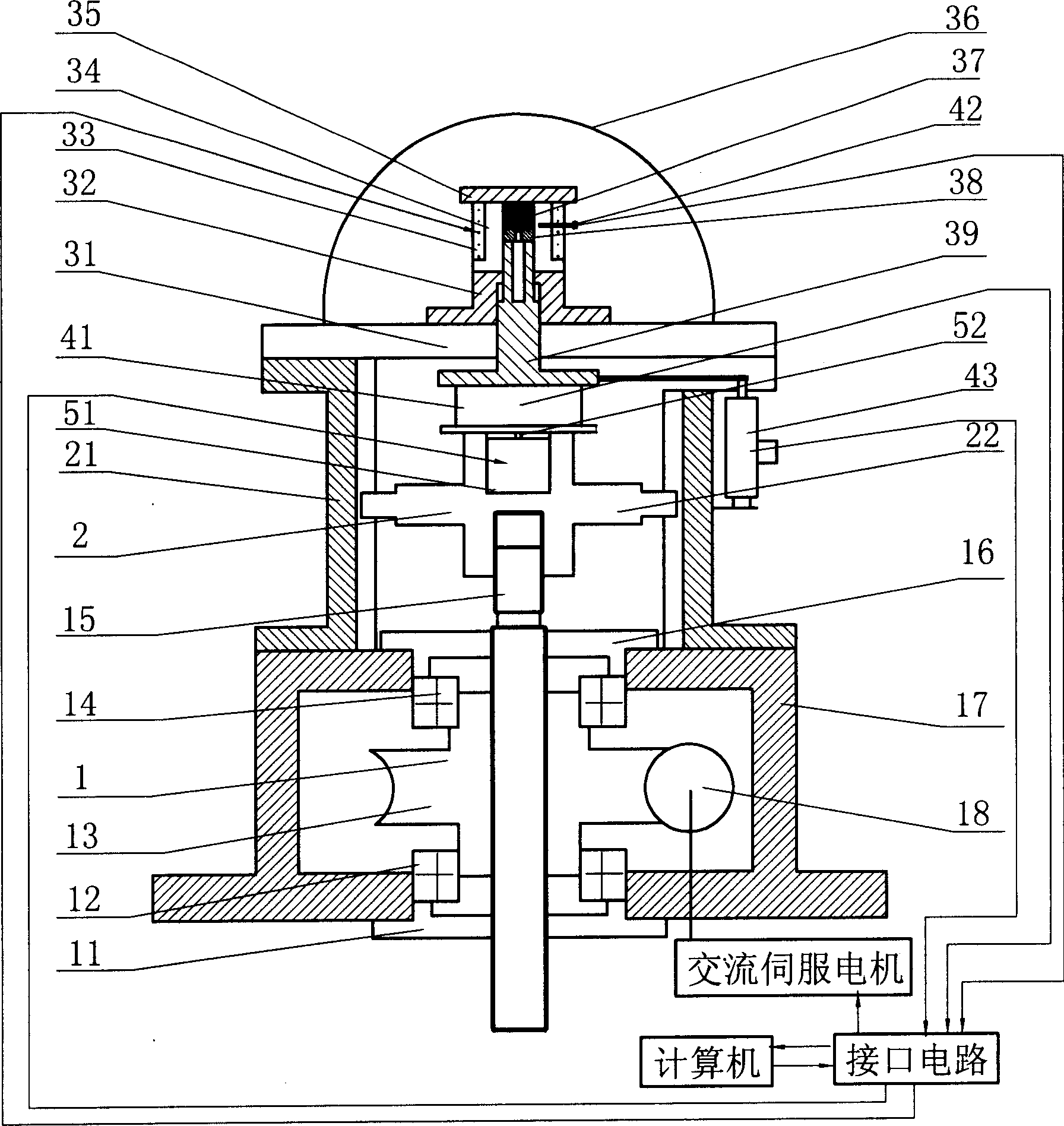
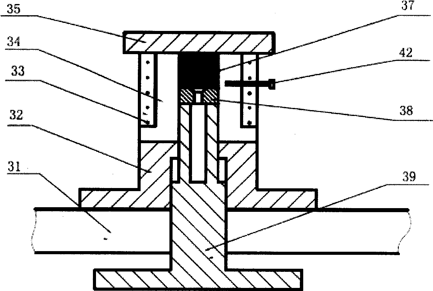
[0018] refer to Figure 1~3 , the present invention consists of a deceleration mechanism, a guiding mechanism, a forming mechanism and a sensor assembly. Speed ​​reduction mechanism comprises lower bearing cover 11, lower bearing 12, worm gear nut 13, upper bearing 14, screw rod 15, upper bearing cover 16, reduction box casing 17 and worm screw 18. The worm wheel nut 13 is connected with the reduction box body 17 through the upper and lower bearings, the screw rod 15 is screwed with the worm wheel nut 13, the inner rings of the lower bearing 12 and the upper bearing 14 are in interference fit with the worm wheel nut 13, and the outer rings of the lower bearing 12 and the upper bearing 14 are in interference fit. The ring is in interference fit with the reduction box casing 17.

[0019] The guide mechanism includes a guide rail 21 and a differential nut 22 . The guide rail 21 is fixedly connected to the reduction box body 17, four bosses are evenly distributed on the outer ri...


PUM


Abstract

The super plasticity extruding formation apparatus for miniature parts includes a reduction mechanism, a guide mechanism, a forming mechanism, a piezoelectric ceramic driver, an AC servo motor, a sensor assembly and a computer. Worm gear and differential nut are used to produce force driving the mold, so that the extruding formation apparatus has increased stroke and free feeding in millimeter level. The piezoelectric ceramic driver is used in trimming the extruding stroke just before finishing the extrusion, so as to reach the aim of precise extrusion in micron level.

Description

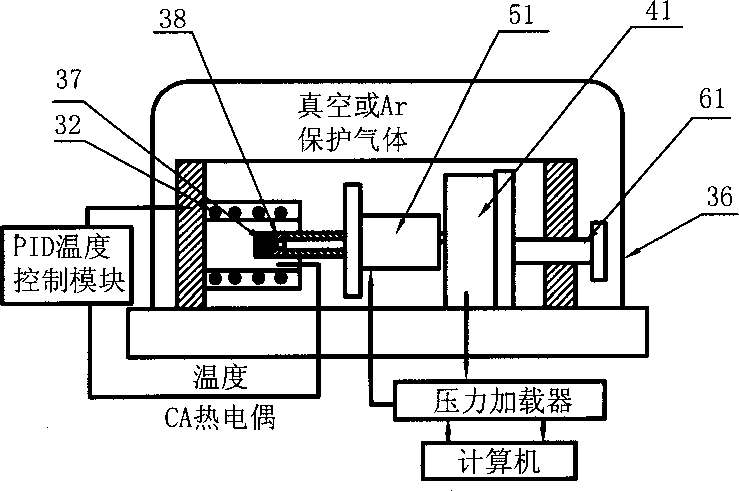
technical field [0001] The invention relates to a superplastic extrusion forming device, in particular to a superplastic extrusion forming device for tiny parts. Background technique [0002] refer to image 3 , Figure 4 , Document 1 ""Superplastic backward micro extrusion of micro-parts for micro-electro-mechanical systems" yasunori Saotome Hiroyuki iwazaki Journal of material processing technology 119 2001 307-311" introduces a micron-scale parts forming device fixed on a platform 31 There is a vacuum cover 36, and all molding and adjustment facilities are in the vacuum cover 36, and the vacuum cover 36 is a vacuum environment or filled with an inert gas. The precision knob 61 passes through the fixed frame 62 and is fixedly connected with the movable plate 63. The pressure sensor 41 is placed on the platform 31, one end of which is in contact with the movable plate 63, and the other end is in contact with the piezoelectric ceramic driver 51, and the piezoelectric cerami...

Claims


Application Information

Patent Timeline
IPC IPC(8): B30B1/00B30B15/00B30B15/34
Inventor 齐乐华杨方毛军孙振锋陈勇王华龙
Owner NORTHWESTERN POLYTECHNICAL UNIV
Learn More