Low color cast liquid crystal display and its driving method

A liquid crystal display, transistor technology, used in static indicators, instruments, etc., to solve problems such as color shift and different transmittances

Active Publication Date: 2006-08-23
AU OPTRONICS CORP
View PDF0 Cites 35 Cited by
  • Summary
  • Abstract
  • Description
  • Claims
  • Application Information

AI Technical Summary

Problems solved by technology

Depend on figure 2 and image 3 It can be seen that under the same driving voltage or the same gray scale, different viewing angles will lead to different transmittances, so color shift will appear when displaying images

Method used


Image

  • Low color cast liquid crystal display and its driving method
  • Low color cast liquid crystal display and its driving method
  • Low color cast liquid crystal display and its driving method

Examples


Embodiment Construction

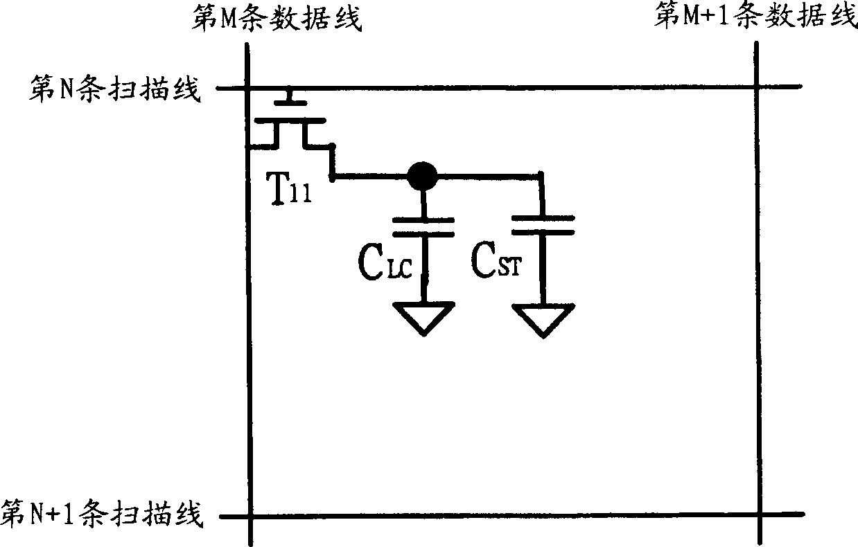
[0030] Please refer to Figure 4 , which shows an equivalent circuit diagram of a pixel of a liquid crystal display according to a preferred embodiment of the present invention. The pixel P is disposed at the intersection of the M th data line and the N th scan line, and the pixel P includes a first sub-pixel SP1 and a second sub-pixel SP2 , a first switch circuit S1 , and a second switch circuit S2 . The first sub-pixel SP1 is composed of liquid crystal capacitor C LC1 and storage capacitor C ST1 Equivalently, the second sub-pixel SP2 is composed of liquid crystal capacitance C LC2 and storage capacitor C ST2 equivalent.

[0031] The first switch circuit S1 includes a thin film transistor T 42 and TFT 43 , while the second switch circuit S2 includes a thin film transistor T 41 . TFT 41 It includes a first gate, a first source and a first drain. The first gate is controlled by the Nth scan line, the first source is coupled to the Mth data line, and the first drain is...


PUM


Abstract

This invention relates to a LCD including multiple scanning lines, multiple data lines, pixels, a first switch circuit and a second switch circuit, in which, said multiple scanning lines include the Nth scanning line and the N+1 scanning lines and N is a positive integer, the pixels include a first sub-pixel and a second sub-pixel, in which, the first switch circuit is coupled to the Nth and the N+1 scanning lines, the first switch circuit controls the second sub-pixel, the second switch circuit is coupled to the Nth scanning line and controls the first sub-pixel displaying red, green, blue or white.

Description

technical field [0001] The present invention relates to a liquid crystal display and its driving method, in particular to a low color shift liquid crystal display and its driving method. Background technique [0002] With the thinner display trend, liquid crystal displays are currently widely used in various electronic products such as mobile phones, notebook computers, and color TV sets. However, in a traditional color liquid crystal display, a pixel is only provided with one driving voltage within a frame period (Frame Period), so that the corresponding liquid crystal presents a specific angle of inclination, which results in color changes as the viewer's viewing angle changes. offset. figure 1 Represents the equivalent circuit of a known pixel, which is set at the intersection of the Mth data line and the Nth scanning line, and the equivalent circuit includes a thin film transistor T 11 , LCD capacitance C LC , and storage capacitor C ST . Such as figure 1 As shown,...

Claims


Application Information

Patent Timeline
Patent Type & Authority Applications(China)
IPC IPC(8): G02F1/133G09G3/36
Inventor 苏振嘉田名峰杨家荣张庭瑞陈伯纶
Owner AU OPTRONICS CORP
Why Eureka
Try Eureka