Electroplating method of terminal and terminal material belt structure

A terminal and strip technology, applied in the field of terminal strip structure, can solve problems such as inconvenience and increase terminal cost, and achieve the effects of convenient electroplating, increased electroplating speed, and convenient operation.

Inactive Publication Date: 2006-08-30
DEYI PRECISION ELECTRONIC IND CO LTD PANYU
View PDF0 Cites 1 Cited by
  • Summary
  • Abstract
  • Description
  • Claims
  • Application Information

AI Technical Summary

Problems solved by technology

Since the terminal 80 is connected to one side of the strip 90, it is very inconvenient to plate precious metals on the contact portion 801 and the welding portion 802 by brush plating. All are plated with precious metals, which will greatly increase the cost of the terminal

Method used


Image

  • Electroplating method of terminal and terminal material belt structure
  • Electroplating method of terminal and terminal material belt structure
  • Electroplating method of terminal and terminal material belt structure

Examples


Embodiment Construction

[0012] The electroplating method and the terminal strip structure of the terminal of the present invention will be further described below with reference to the accompanying drawings.

[0013] Generally, in order to enhance the corrosion resistance, wear resistance and conductivity of the terminal, it is necessary to plate one or more layers of metal on the terminal. The electroplating method of the terminal of the present invention first provides a step of providing a substrate (the substrate is a plate-shaped metal); then a step of punching the substrate out of the terminal and a strip; and finally a step of electroplating on the terminal.

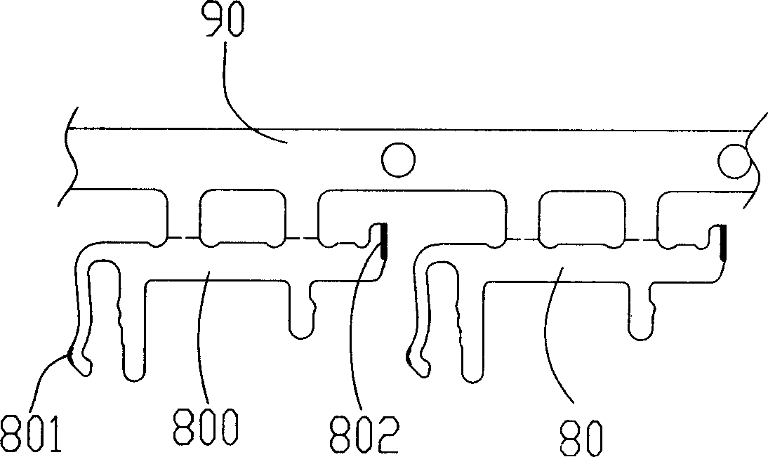
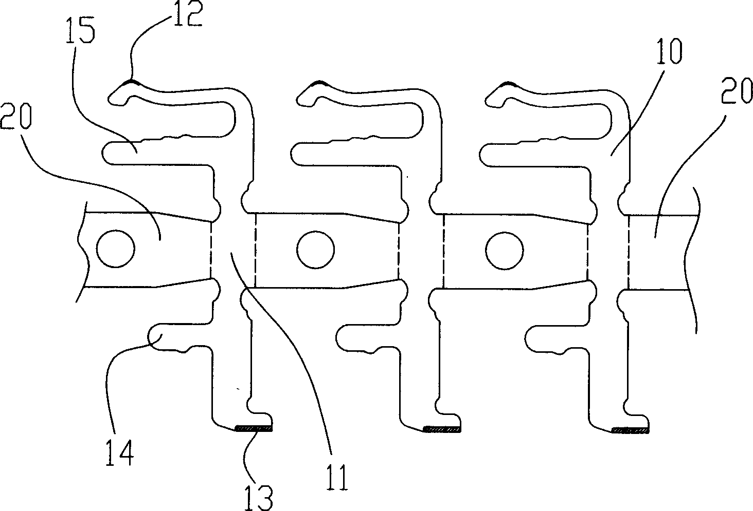
[0014] Such as figure 2 As shown, the terminal strip structure using the above-mentioned electroplating method is stamped from a long strip of plate-shaped metal (not shown), which includes a terminal 10 and a strip 20, wherein the terminal 10 includes a main body 11 that faces from both sides of the main body 11 A contact part 12 and a wel...


PUM


Abstract

The present invention relates to an electroplating method of terminal. Said method includes the following steps: 1. providing base material; 2. punching base material to obtain terminal and its material tape; and 3. electroplating terminal. It is characterized by that said terminal includes two portions of be electroplated, said two portions to be electroplated are respectively positioned in two sides of said material tape.

Description

【Technical Field】 [0001] The invention relates to a terminal electroplating method and a terminal strip structure. 【Background technique】 [0002] The terminal of the electrical connector is generally formed by stamping and forming a base material into the prototype of the terminal, and a material strip that can connect multiple terminals in appropriate positions is produced at the same time during the stamping and forming. The material strip is required to pull the terminal for subsequent Processing processes such as electroplating and secondary molding can mechanize terminal manufacturing and achieve the purpose of improving production efficiency. The existing terminal strip structure is as figure 1 As shown, the terminal 80 is connected to the material strip 90. The terminal 80 includes a main body 800 and a contact portion 801 and a welding portion 802 which are provided at both ends of the main body and can be connected to external electronic components (not shown), in orde...

Claims


Application Information

Patent Timeline
Patent Type & Authority Applications(China)
IPC IPC(8): B23K1/20
Inventor 朱德祥
Owner DEYI PRECISION ELECTRONIC IND CO LTD PANYU
Why Eureka
Try Eureka