Supercharge Your Innovation With Domain-Expert AI Agents!

Connecting device, combined member and use thereof

A technology for connecting devices and combining components, which is applied to educational appliances, instruments, teaching models, etc., and can solve the problems of easy loosening and shrinking of the combination.

Inactive Publication Date: 2006-08-30
IND TECH RES INST +1
View PDF0 Cites 3 Cited by
  • Summary
  • Abstract
  • Description
  • Claims
  • Application Information

AI Technical Summary

Problems solved by technology

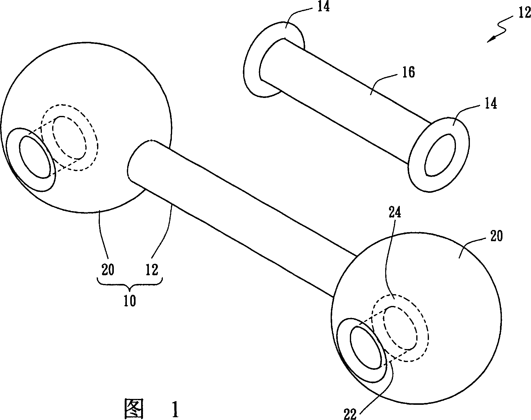
Furthermore, after the insertion pin 12 and the ball 20 of the composite member 10 are assembled and disassembled many times, the size of the annular convex portion 14 is likely to be reduced due to wear, while the size of the annular concave portion 24 is likely to be reduced due to wear. and increased, causing the combination of the two to be easily loosened

Method used


Image

  • Connecting device, combined member and use thereof
  • Connecting device, combined member and use thereof
  • Connecting device, combined member and use thereof

Examples


Embodiment Construction

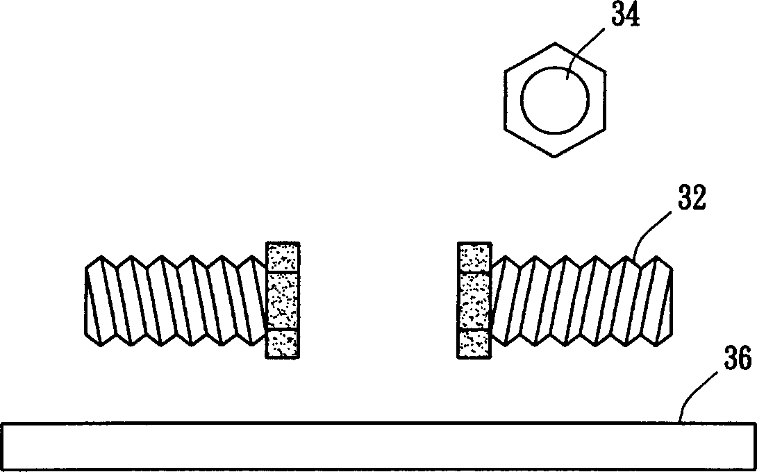
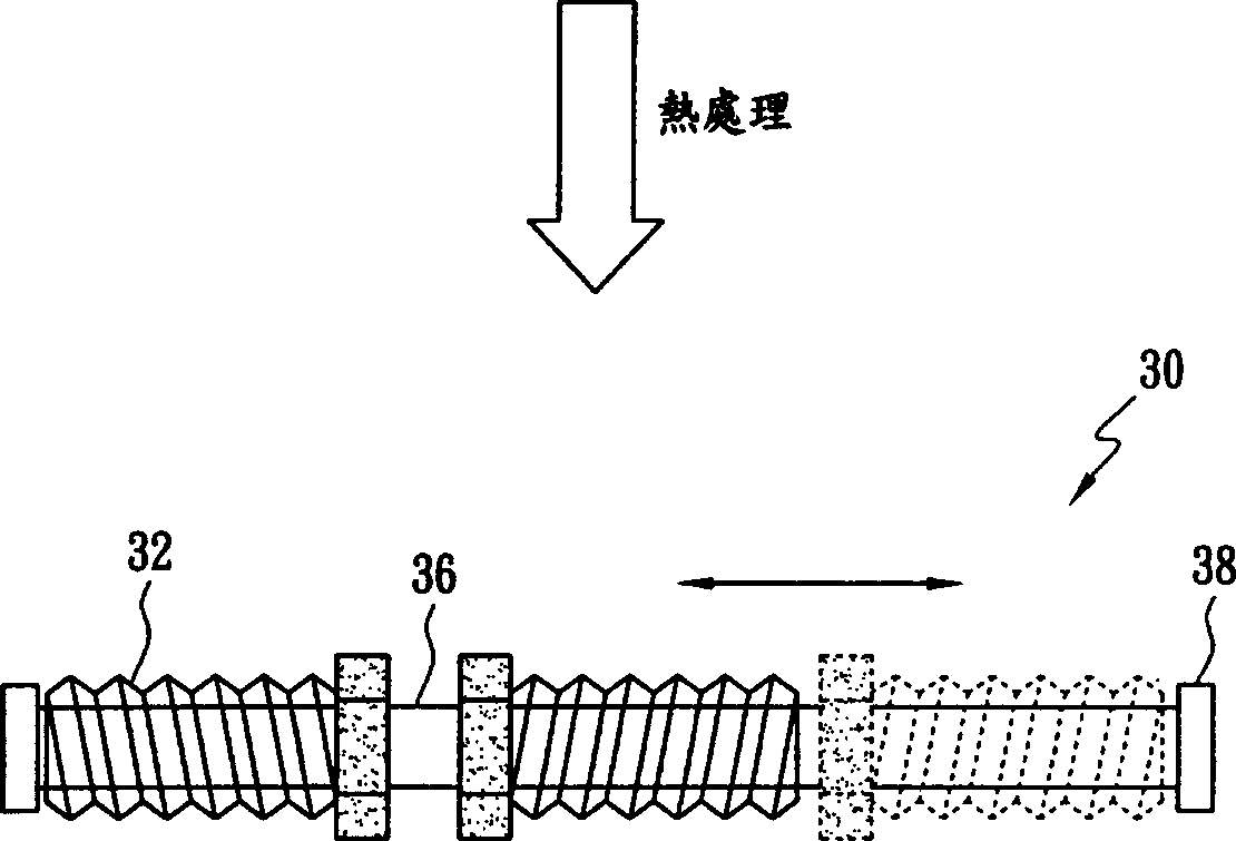
[0065]Referring to FIG. 2, FIG. 2(a) and FIG. 2(b) illustrate the first connecting device 30 of the present invention. The connection device 30 comprises two bolts 32 with a hollow 34 and a bearing member 36 slidably placed in the hollow 34, wherein the end of the bearing member 36 has a protrusion with a size (diameter) larger than the hollow 34 38. The preparation method of the connecting device 30 is to first place the bearing part 36 in the hollow 34 of the bolt 32, then perform a heat treatment to soften the end of the bearing part 36, and apply force to the end of the bearing part 36 to push inward. The protrusions 38 are formed to prevent the bolts 32 from detaching from the bearing member 36, but allow the bolts 32 to move between the two protrusions 38, as shown in FIG. 2(b). Preferably, the bolt 32 and the bearing part 36 of the connecting device 30 are made of plastic or metal.

[0066] image 3 It is the first combined component 40 of the present invention. The ...


PUM


Abstract

The invention discloses a connecting device and the combined component thereof, comprising a main body with plural screw holes and a connecting device able to be connected to the main body, where the connecting device comprises at least a hollow bolt which is screwed with the screw hole and fixed, and has plural branch bearing components placed in the hollow in a sliding mode, where the end of the branch has a salient whose size is greater that the diameter of the hollow. And parts of the combined component are connected by the bolt and screw hole, uneasy to loosen. In addition, the combined component can selectively comprise conductive part, luminous layer and protective layer so as to have light-emitting ability. And the invention discloses the use of the combined component.

Description

1. Technical field [0001] The present invention relates to a connection device and its composite component and its application, more particularly to a connection device and its composite component which cannot be loosened due to wear and tear. 2. Background technology [0002] FIG. 1 is a schematic illustration of a known composite member 10 . The combined component 10 includes a pin 12 and a ball 20 . The end of the spigot 12 has an annular protrusion 14 whose size is greater than that of the middle portion 16 . The ball 20 has holes 22 each having an annular indentation 24 . When assembling the spigot 12 and the ball 20 , the user must forcefully squeeze the annular protrusion 14 of the spigot 12 into the annular indentation 24 of the spheroid 20 . On the contrary, if the combination member 10 is to be disassembled, the user must forcefully pull out the annular protrusion 14 of the spigot 12 from the annular recess 24 of the ball 20 . Since one spigot 12 can connect tw...

Claims


Application Information

Patent Timeline
Patent Type & Authority Applications(China)
IPC IPC(8): G09B23/26
Inventor 张上嘉
Owner IND TECH RES INST
Features
  • R&D
  • Intellectual Property
  • Life Sciences
  • Materials
  • Tech Scout
  • Unparalleled Data Quality
  • Higher Quality Content
  • 60% Fewer Hallucinations
Learn More