Integrated controller for meter and electrical appliance

A comprehensive control and integrated technology, applied in circuit devices, emergency protection circuit devices, emergency protection devices, etc., can solve problems such as complex system wiring, waste of platinum resources, and no isolation measures

A comprehensive control and integrated technology, applied in circuit devices, emergency protection circuit devices, emergency protection devices, etc., can solve problems such as complex system wiring, waste of platinum resources, and no isolation measures

CN1825729AInactive Publication Date: 2006-08-30张 世兴

Image

  • Integrated controller for meter and electrical appliance
  • Integrated controller for meter and electrical appliance
  • Integrated controller for meter and electrical appliance

Examples


Embodiment Construction

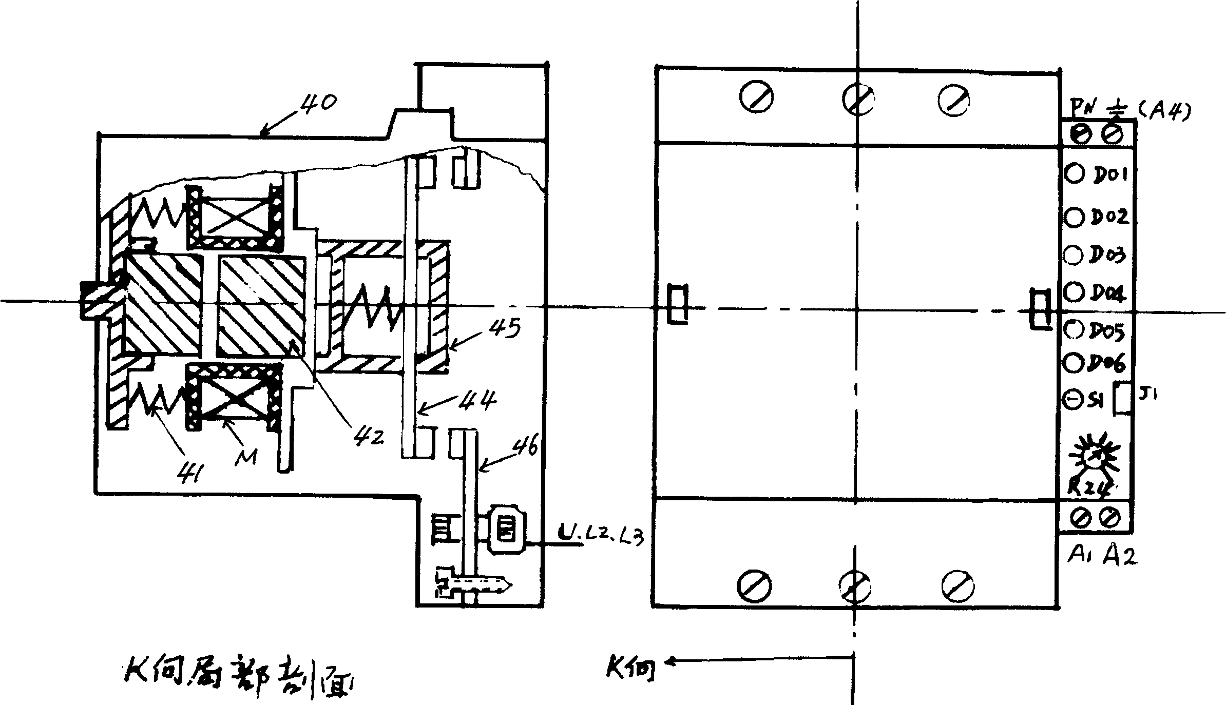
[0035] Below in conjunction with accompanying drawing, the embodiment of the integrated instrument of the present invention, electric appliance integrated control device is described further:

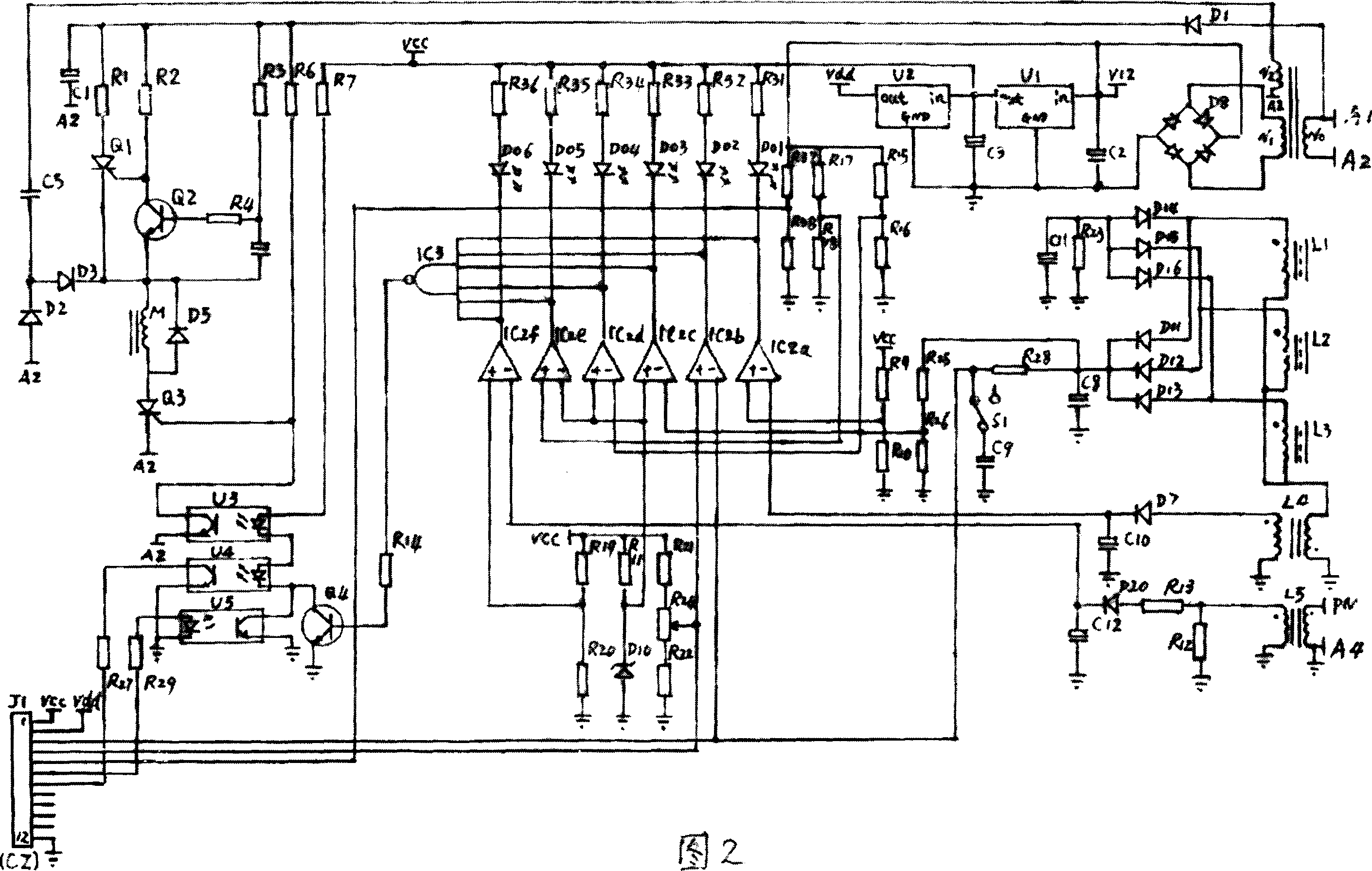
[0036] according to figure 1 The schematic diagram of the shell structure is shown; the spring (41), the iron core (42), the coil M, and the bracket (45) equipped with the moving contact (44) are sequentially loaded into the fault display window and the fault display mark. Main body housing (40), then install the static contact assembly (46) with the current sensor on one side of the static contact bridge. The static contact assembly (46) is based on the static contact bridge as the primary winding and is wound with the secondary winding After the static contact assembly (46) is installed, the electronic control circuit board with fault display is loaded into the side of the housing, and the fault display light-emitting diodes D01-D06 are respectively separated from the housing (40) T...


PUM


Abstract

This invention relates to a combined control device for integrated instruments and electric appliances composed of a shell with a faulty display window and labels, an electronic control circuit, an intelligent expanding module circuit, a moving and static contactor component with a current sensor at the side of a static contact bridge, an iron core, a coil and a spring, which realizes multiple kinds of protections and fault display by the electronic control circuit and has the function of power saving, a photo electric isolation technology is applied for its high voltage drive and low voltage signal circuit and the I / O expanding interface and an intelligent expansion module are applied to enrich the function of the display and control of the instrument.

Description

technical field [0001] The invention belongs to the field of low-voltage electrical appliances and automatic instruments. Background technique [0002] In the field of traditional industrial automation control, there are mainly two categories of electrical appliances and instruments. Among them, low-voltage electrical components mainly include AC contactors, thermal relays, current relays, voltage relays, time relays, leakage protectors, phase failure protectors, etc. These products Single function, generally can not work alone, and automation instrument is mainly divided into detection instrument, display instrument, control instrument and actuator, they are responsible for the detection, display, control and other functions of industrial physics, chemistry, length, weight, electricity and other parameters , is the sensory and nervous system of the automation system. They do not have the ability to directly drive the motor or control high-power equipment. They must cooperat...

Claims


Application Information

Patent Timeline
30 Aug 2006
Publication
CN1825729A
IPC
H02H3/08; H02H3/10; H02H3/14; H02H3/20; H02H3/24; H02H3/32; H01H71/00
Inventors
张世兴