
Pump comprising an integrated engine

An electric motor and integrated technology, applied in liquid fuel engines, parts of pumping devices for elastic fluids, machines/engines, etc., can solve problems such as damage to sliding bearings and rotor chambers, single-sided wear of sliding bearings, etc.

Active Publication Date: 2006-08-30
BOSCH SIEMENS HAUSGERATE GMBH
View PDF0 Cites 20 Cited by
  • Summary
  • Abstract
  • Description
  • Claims
  • Application Information

AI Technical Summary

Problems solved by technology

Damage to plain bearings and rotor chambers due to contamination and erosion by water
Furthermore, conventional constructions have the disadvantage that the plain bearings are subject to one-sided wear due to the weight of the rotor

Method used


Image

  • Pump comprising an integrated engine
  • Pump comprising an integrated engine

Examples


Embodiment Construction

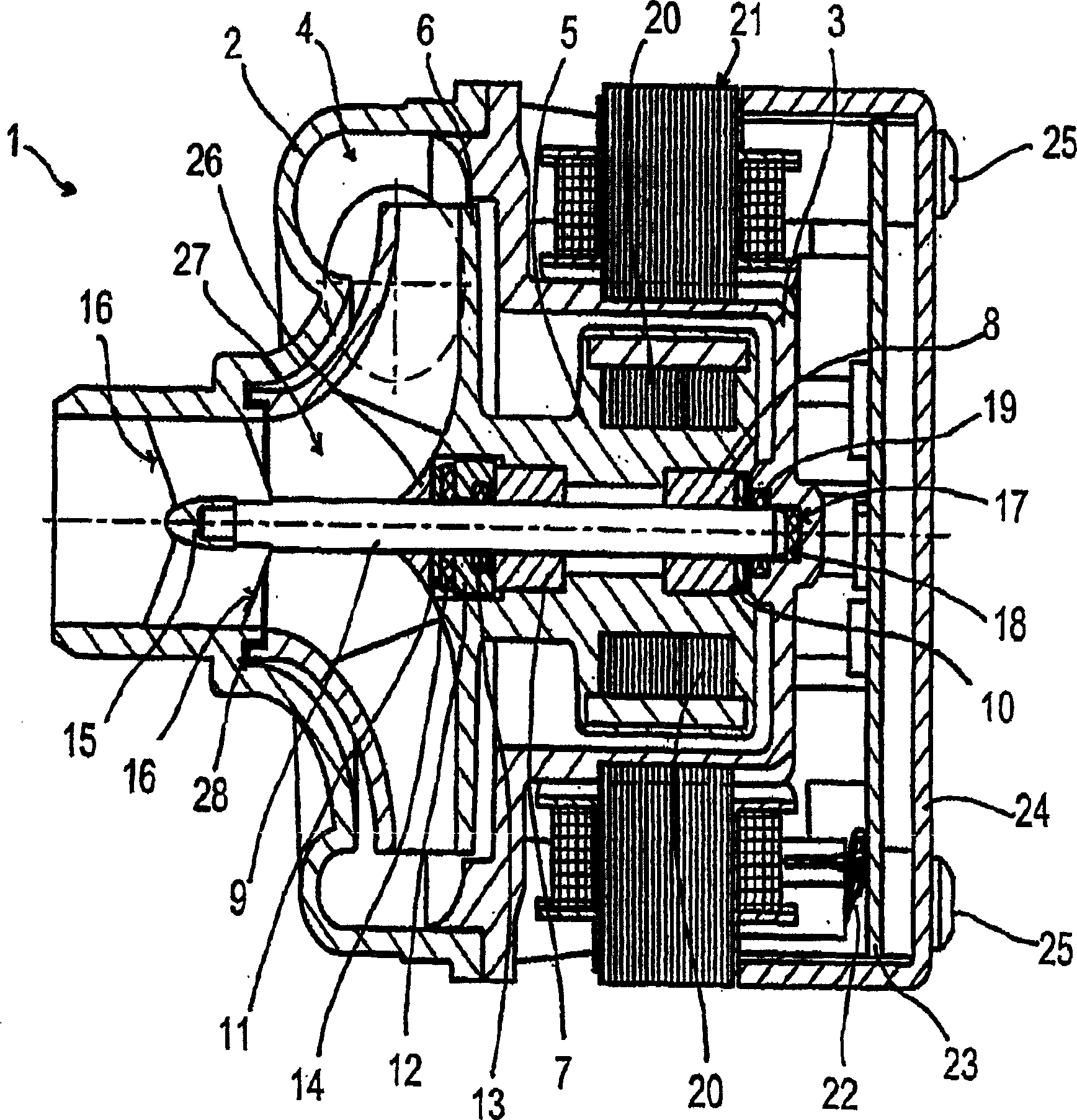
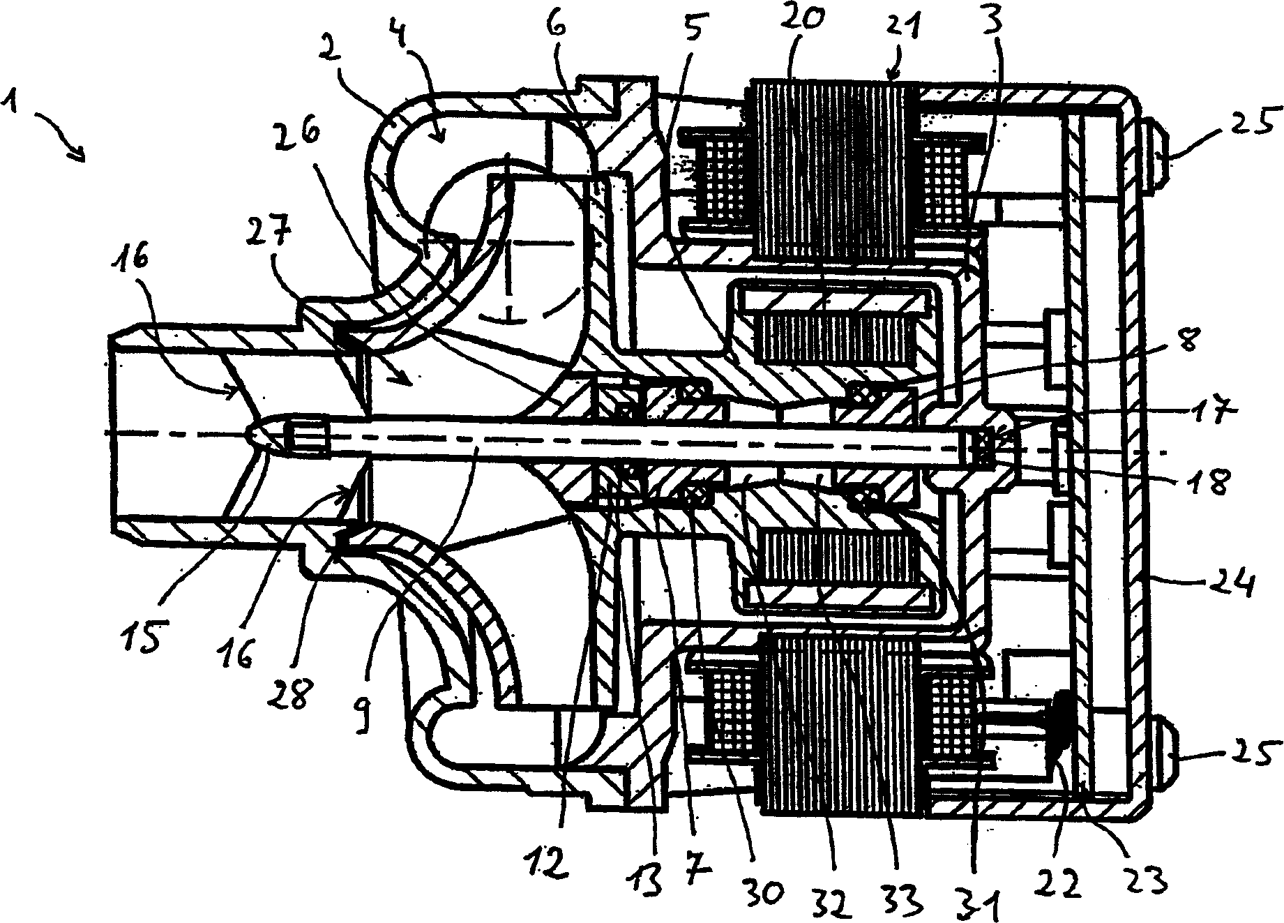
[0017] in accordance with figure 1 and figure 2 , The housing of the pump 1 is composed of a front housing shell 2 and a pot-shaped end cover 3, which are connected in a form-fitting manner. The casing of the pump 1 forms an integral pump chamber 4 in which a rotor 5 and an impeller 6 are included. The impeller 6 is preferably integrally formed on the rotor 5 .

[0018] The rotor 5 is rotatably supported on the shaft 9 via a front sliding bearing 7 adjacent to the impeller 6 and via a rear sliding bearing 8 adjacent to the end cover 3 . In order to prevent the rotor 5 from moving axially on the shaft 9, according to figure 1 , the rotor 5 is positioned at each of its ends by a locking ring 10 , 11 . In addition, the rotor 5 has an end bearing 12 at its front end close to the impeller 6 to reduce axial displacement, which has a seat for an O-ring 13 between the end bearing 12 and the slide bearing 7 . The sliding bearing 7 is sealed against the liquid inlet, in particular...


PUM


Abstract

The single-part chamber (4) of the pump (1) surrounds a motor rotor (5).

Description

technical field [0001] The invention relates to a pump with an integral electronically commutated wet rotor motor. Background technique [0002] In conventional constructions of pumps with integral electronically commutated motors, the shaft rotates together with the rotor of the motor in the rotor chamber, while the impeller of the pump rotates in the hydraulic chamber. Between the two chambers is the bearing endshield with the plain bearing for supporting the shaft and the sealing rubber to protect the plain bearing from water contamination and corrosion. The bearing cover prevents water flow from the hydraulic chamber into the rotor chamber. If the sealing rubber fails, water can enter the rotor chamber. Damage to plain bearings and rotor chambers can occur due to contamination and erosion by water. Furthermore, conventional constructions have the disadvantage that the slide bearings are subject to one-sided wear due to the weight of the rotor. Contents of the invent...

Claims


Application Information

Patent Timeline
Patent Type & Authority Applications(China)
IPC IPC(8): F04D13/06F04D29/42
CPCF04D13/064F04D13/0633F04D29/426F04D13/0606F04D13/06
Inventor M·卡拉夫斯基P·德菲利皮斯
Owner BOSCH SIEMENS HAUSGERATE GMBH
Learn More