Tuning improvements in 'inverted-L' planar antennas

A planar antenna and planar antenna technology, applied to antennas, resonant antennas, and devices that enable antennas to work in different bands at the same time, can solve problems such as detuning

Inactive Publication Date: 2006-08-30
NXP BV
View PDF0 Cites 11 Cited by
  • Summary
  • Abstract
  • Description
  • Claims
  • Application Information

AI Technical Summary

Problems solved by technology

[0006] A disadvantage that has been found to mount PIFAs inside the housing of a cellular phone and place

Method used


Image

  • Tuning improvements in 'inverted-L' planar antennas
  • Tuning improvements in 'inverted-L' planar antennas
  • Tuning improvements in 'inverted-L' planar antennas

Examples


Embodiment Construction

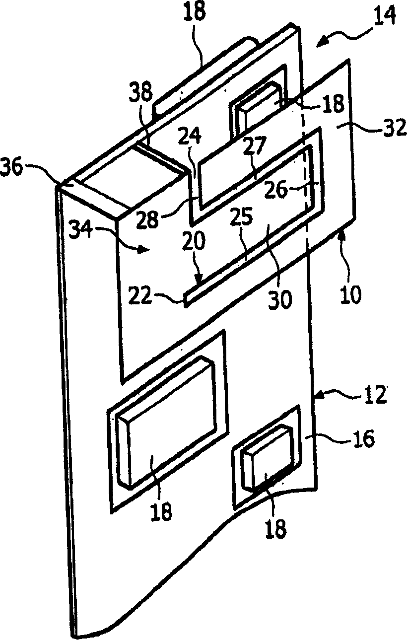
[0025] due to attachment figure 1 It has already been introduced in the background technology part of this specification, so it will not be repeated here.

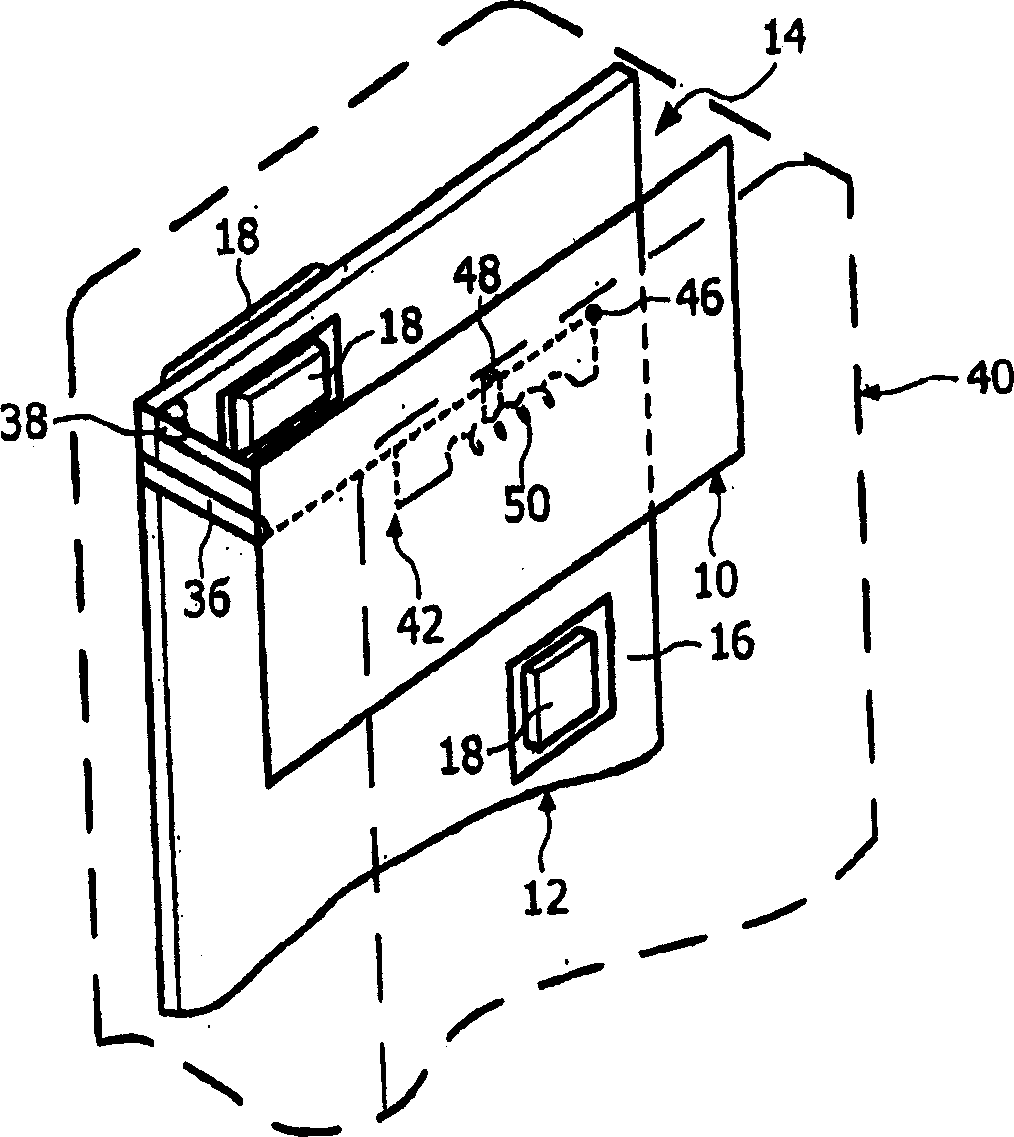
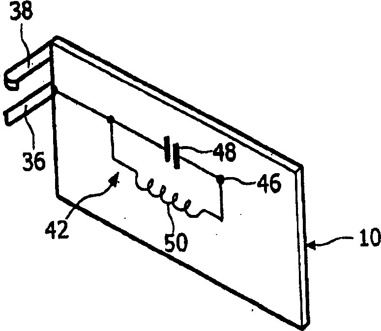
[0026] attached figure 2 And attached image 3 Denotes a portable communication device, such as a portable radiotelephone, which includes a housing 40 housing a PIFA 10 coupled via a feed stub 36 to an rf circuit (not shown) mounted on a PCB 12 . A shorting stud 38 elastically contacts the ground plane 16 on the PCB 12 . The short-circuit stub 38 realizes impedance transformation. The parallel LC circuit 42 mounted on the back of the antenna or on the substrate carrying the antenna is connected in series between the feeding stub 36 and the feeding pin 46 on the planar antenna. In practice, the feed pin 46 may be close to the feed pin 36 so as not to interfere with the operation of the antenna 10 . The values ​​of the inductance 50 and capacitance 48 of the circuit are chosen to reactively tune the antenna. In the ca...


PUM


Abstract

A communications apparatus, such as a portable radiotelephone, comprises a housing (40) containing a printed circuit board (PCB) (12) having a ground plane (16) and electronic components in rf shields (18) thereon. A planar antenna (10), for example a planar inverted-L antenna (PILA), is mounted spaced from the ground plane and a dielectric (14), for example, air, is present in a space between the PCB and the planar antenna. A feed (36) couples the planar antenna (10) to the rf components. The feed comprises parallel L-C resonator circuit components (42), a transmission line, or any other predominantly reactive network for reactively tuning the antenna. In the case of a dual band antenna the components are selected so that a lower frequency is tuned inductively and a higher frequency is tuned capacitively. The components, which may be discrete or distributed, are mounted on the PCB or a part of the planar antenna structure which is not subject to detuning by the user in normal operation of the apparatus.

Description

technical field [0001] This invention relates to or relates to improvements in planar antennas and in particular, but not exclusively, to dual-band antennas for use in portable telephones. Such phones can operate in compliance with the GSM and DCS 1800 standards. Background technique [0002] PIFAs (Planar Inverted-F Antennas) are widely used in portable antennas because of their very low SAR (Specific Absorption Ratio), which means less transmitted energy is lost to the head, and PIFA antennas are They are compact, which allows them to be mounted above the telephone circuitry, making more efficient use of the space inside the telephone housing. [0003] in the attached drawings figure 1 A three-dimensional schematic diagram of PIFA 10 is given in . The PIFA 10 is separated from a printed circuit board (PCB) 12 by a medium 14, which in the example shown is air. Typically, electronic components in rf shields (also called rf cans) 18 are mounted on both sides of PCB 10 , a...

Claims


Application Information

Patent Timeline
IPC IPC(8): H01Q9/04H01Q1/24H01Q5/10
CPCH01Q9/0421H01Q1/243H01Q9/04H01Q13/08H01Q1/24
Inventor K·R·博伊尔
Owner NXP BV
Why Eureka
Try Eureka