
Switching control device for primary side control output current of power supply

A power supply and control device technology, which is applied to battery circuit devices, circuit devices, current collectors, etc., can solve the problem of increasing costs, the switching controller cannot control the output current of the power supply accurately, and the constant current curve cannot be achieved. and other problems to achieve the effect of reducing the output current

Active Publication Date: 2006-09-06
SYST GEN
View PDF0 Cites 9 Cited by
  • Summary
  • Abstract
  • Description
  • Claims
  • Application Information

AI Technical Summary

Problems solved by technology

According to the technology disclosed so far, the switching controller provided on the primary side of the power supply cannot precisely control the output current of the power supply, and thus cannot achieve a constant current curve with a straight line characteristic
Furthermore, in order to achieve the aforementioned constant current curve, a current loop must be added on the secondary side of the power supply to achieve constant current control. In this way, the cost must be increased

Method used


Image

  • Switching control device for primary side control output current of power supply
  • Switching control device for primary side control output current of power supply
  • Switching control device for primary side control output current of power supply

Examples


Embodiment Construction

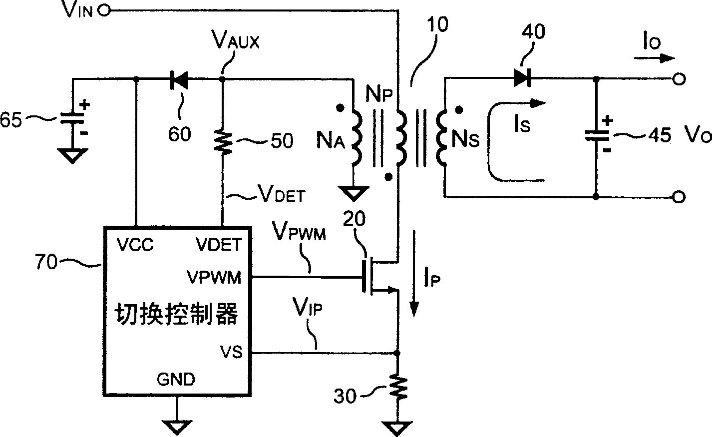
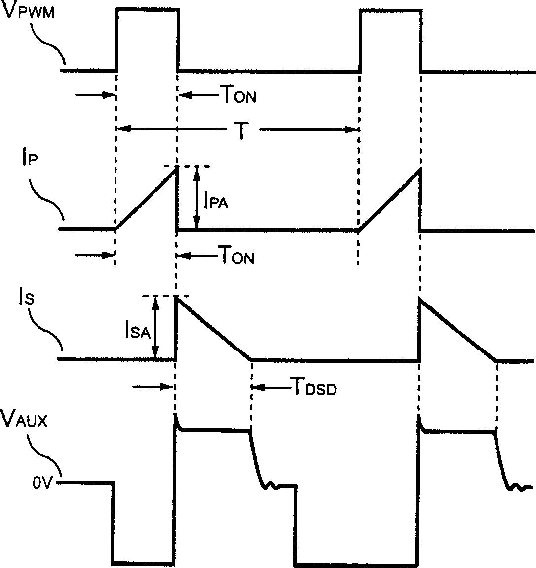
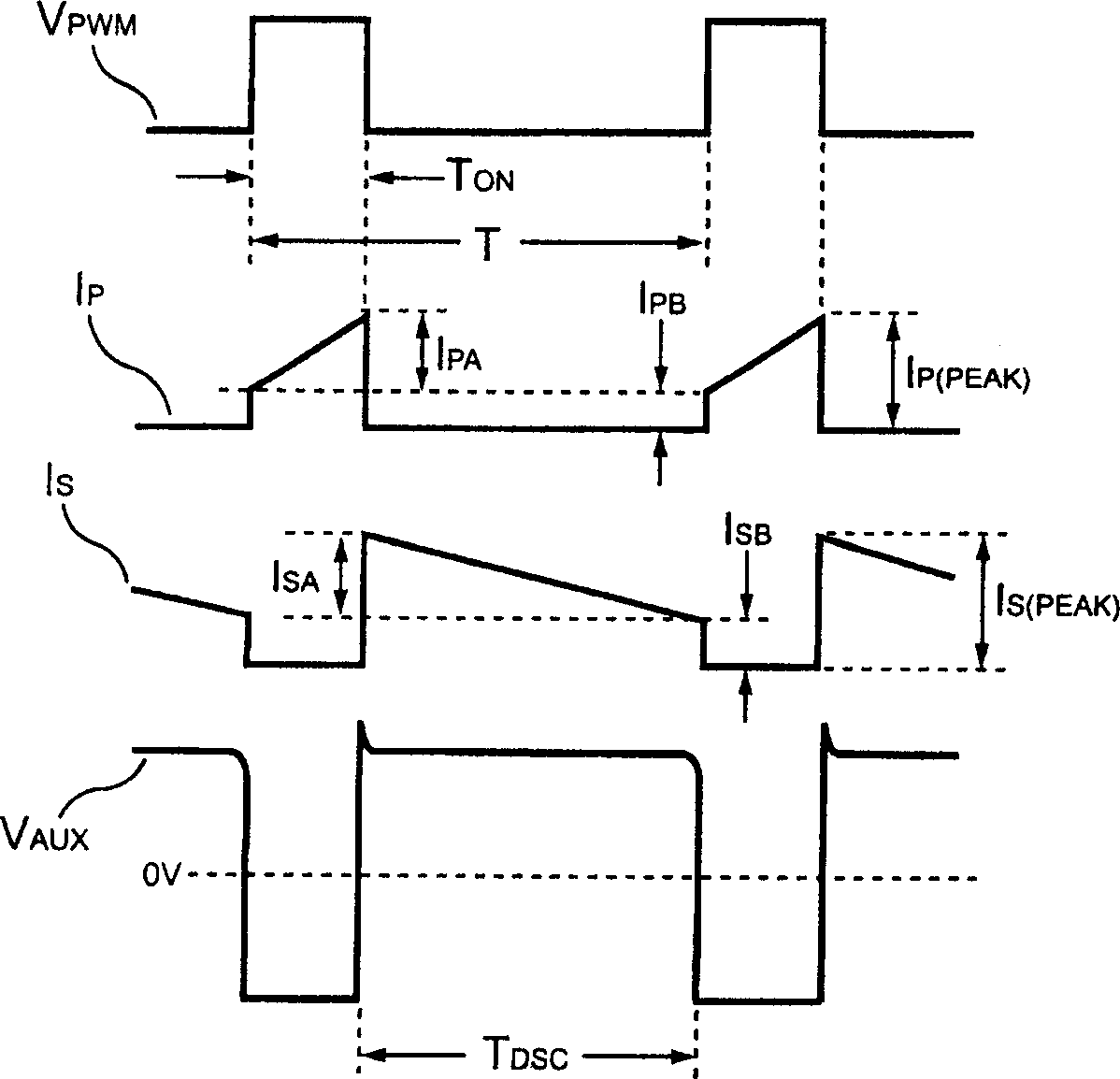
[0049] refer to figure 1 , which is a schematic diagram of the switching control device of the present invention disposed on the power supply. The power supply includes a transformer 10, the transformer 10 has an auxiliary winding N A , primary side winding N P , and the secondary side winding N S . In order to stably adjust the output voltage of the power supply V O with output current I O , a switching controller 70 generates a switching signal V PWM The switching operation of the transformer 10 is performed by the switching transistor 20 .

[0050] The switching controller 70 includes a supply terminal VCC, a voltage detection terminal VDET, a ground terminal GND, a current detection terminal VS and an output terminal VPWM. The output terminal VPWM outputs the switching signal V PWM . The voltage detection terminal VDET is connected to the auxiliary winding N through a resistor 50 A , to detect the reflected voltage V AUX , the reflected voltage V AUX The capaci...


PUM


Abstract

The present invention provides switching type controller, used in power supply delivery unit primary side for controlling current output. It includes waveform detector, discharge time detector, oscillator, integrator, error amplifier pulsewidth comparer. The current output of power supply delivery unit can be stable adjusted on primary side.

Description

technical field [0001] The present invention relates to a switching control device, in particular to a switching control device applied to a power supply. Background technique [0002] Currently, power supplies that can provide stable voltage and current have been widely used in various electronic devices. Based on safety requirements, an off-line power converter must provide galvanic isolation between its primary side and secondary side. In many charger-related applications, the requirements for constant current curve and low cost are very high. According to the currently disclosed technology, the switching controller provided on the primary side of the power supply cannot precisely control the output current of the power supply, and thus cannot achieve a constant current curve with a straight line characteristic. Furthermore, in order to achieve the aforementioned constant current curve, a current loop must be added on the secondary side of the power supply to achieve co...

Claims


Application Information

Patent Timeline
Patent Type & Authority Applications(China)
IPC IPC(8): H02J7/04
Inventor 杨大勇
Owner SYST GEN
Learn More