Apparatus of assemble and disassemble fuel injection valve

A fuel injection valve and fuel technology, which is applied to fuel injection devices, special fuel injection devices, charging systems, etc., can solve problems such as shearing of nozzle clamping pins, and achieve the effect of easy operation.

Active Publication Date: 2006-09-13
ROBERT BOSCH GMBH
View PDF0 Cites 4 Cited by
  • Summary
  • Abstract
  • Description
  • Claims
  • Application Information

AI Technical Summary

Problems solved by technology

If the nozzle clamping nut is simply unscrewed, due to the high clamping force the nozzle turns with it and the clamping pin is sheared off

Method used


Image

  • Apparatus of assemble and disassemble fuel injection valve
  • Apparatus of assemble and disassemble fuel injection valve
  • Apparatus of assemble and disassemble fuel injection valve

Examples


Embodiment Construction

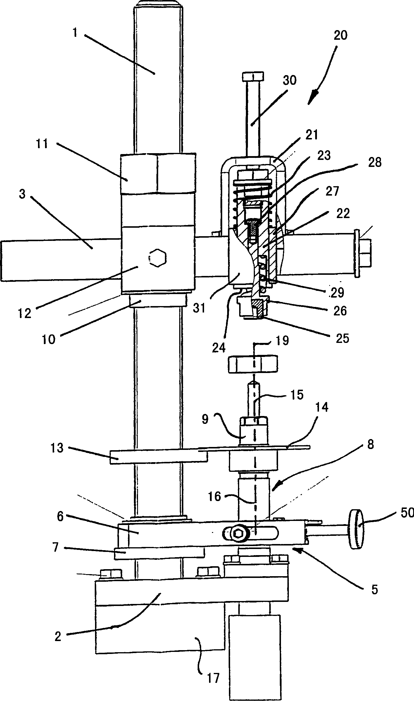
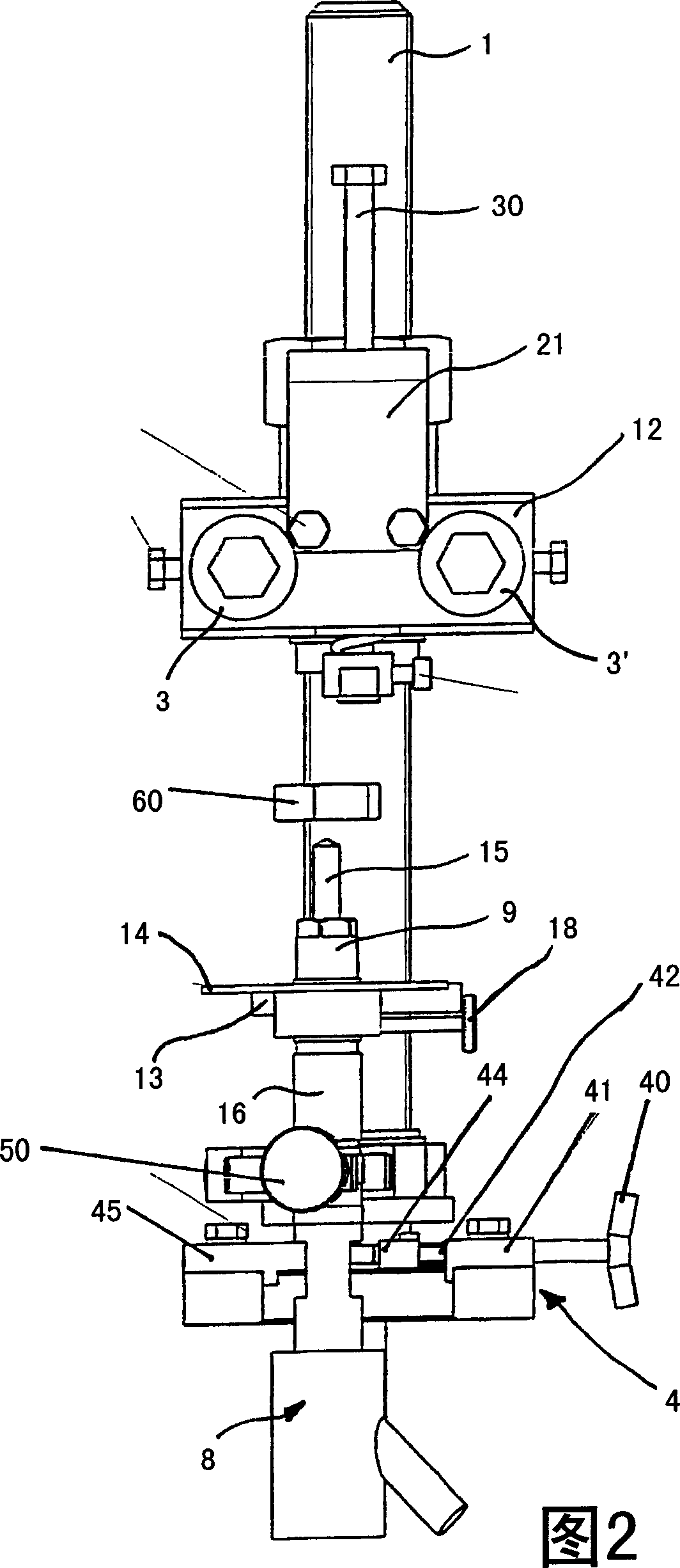
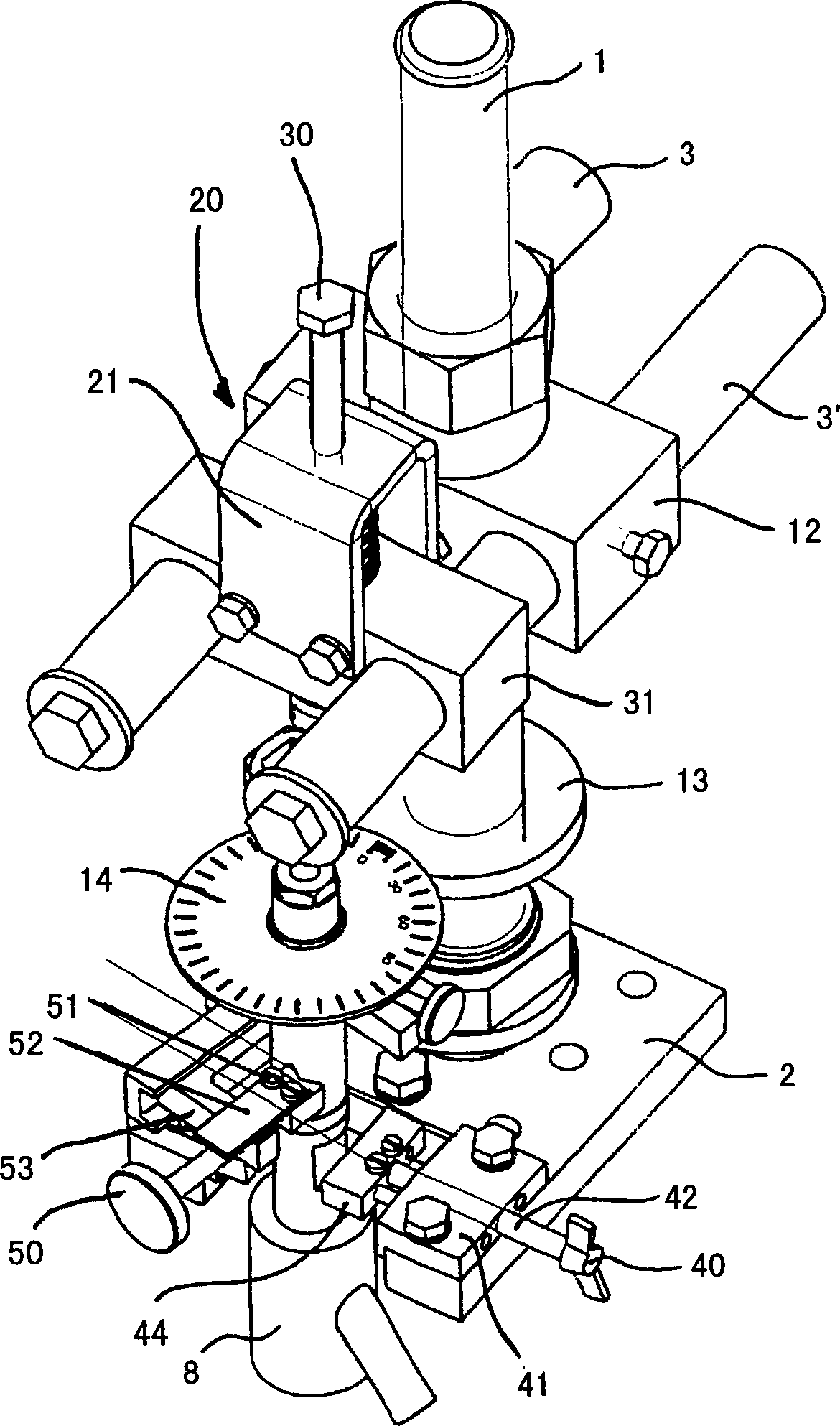
[0023] figure 1 A side view of the device of the present invention is shown in . Figure 2 shows a 90° rotated view of the device, image 3 A perspective view of the same device is shown, whereby all three figures are explained together below, wherein it should be noted that some parts of the device are only visible in one or two of these figures. The device has a basic frame comprising a guide bar 1 and a base plate 2 , wherein the guide bar 1 is threaded over its entire length. A holding element 17 can be fastened to the base plate 2 so that the device can be clamped in a vice. If the device is to be fastened directly on a table, there are holes in the base plate 2 for this purpose. A first holding device 4 for a fuel injection valve is screwed on or otherwise fastened to the base plate 2 , an injector 8 is shown here as an example, which is used in a common rail injection system. The first clamping device 4 comprises a wing nut 40 by means of which a screw 42 guided in a...


PUM


Abstract

The device is for assembling and disassembling fuel injecting valve including one fuel nozzle and one holder, and the nozzle possesses one longitudinal axis and may be pressed axially onto the holder with one holding nut. The device includes one holding unit to fix the fuel injecting valve in the holder, and one nozzle holding part for introducing one longitudinal force to the nozzle. Therein, one clamping unit is used to generate one pre-holding force on the nozzle holding part for convenient assembling and disassembling of the fuel injecting valve.

Description

technical field [0001] The invention relates to a device for assembling and disassembling fuel injection valves. Background technique [0002] In modern diesel engines, fuel is injected directly into the combustion chamber at high pressure by a fuel injection valve. Fuel injection valves are used in various injection systems, for example in common rail systems or in so-called integral injectors (UI), also known as pump-nozzle units, in this In an integral injector, the fuel injection valve and the pump form a unit. The fuel injection valve consists of several parts, essentially a nozzle in which injection holes are formed and a nozzle needle which closes or opens the injection holes is arranged in the nozzle, and a holding body comprising A number of other different components and fuel connections are located on the holder. The nozzle is pressed against the holding body via a nozzle clamping nut, wherein a suitably high tightening torque is required in order to achieve a ...

Claims


Application Information

Patent Timeline
Patent Type & Authority Applications(China)
IPC IPC(8): B23P19/04
CPCB23P19/04F02M61/168F02M2200/852F02M57/02
Inventor 京特·毛德雷尔赖因哈德·霍斯迪尔克·德赫费尔
Owner ROBERT BOSCH GMBH
Why Eureka
Try Eureka