Book binder

A stapler and nail groove technology, applied in the direction of binding, etc., can solve the problems of affecting safe use, large spring pressure, troublesome stapling, etc., and achieve the effects of improving work efficiency, safe use and simple structure

Inactive Publication Date: 2006-09-13
卢瑞祺
View PDF0 Cites 0 Cited by
  • Summary
  • Abstract
  • Description
  • Claims
  • Application Information

AI Technical Summary

Problems solved by technology

[0002] There are many types of staplers on the market, but the groove structure of the staples is the same. The staples are placed in the grooves, and a compression spring is arranged behind the staples, and the staples are pushed forward by the compression springs. Move and compress the elastic force of the spring is related to the compression of the spring. The amount of staples will change the compression of the spring. When there are more staples loaded, the spring pressure is high, and when there are few staples, the spring pressure is small. The pressure change will cause the nail row to break, and there is a certain interval between the nail and the nail groove. The broken nail row will make the positio

Method used


Image

  • Book binder

Examples


Embodiment Construction

[0016] The present invention will be described in further detail below in conjunction with the accompanying drawings and embodiments.

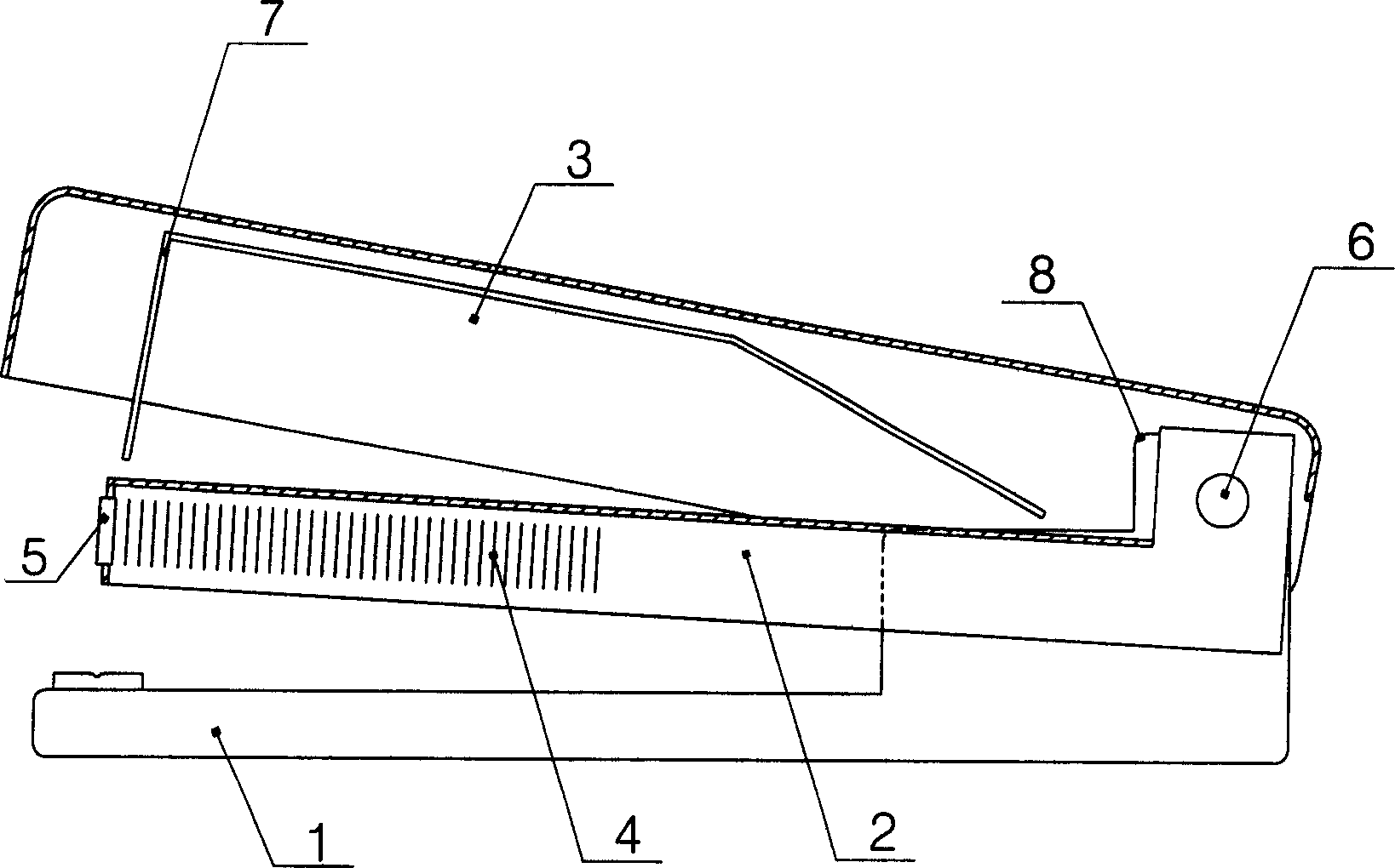
[0017] Such as figure 1 As shown, the stapler of the present invention comprises a base 1, a nail groove 2 and an upper cover 3, and the upper cover 3 is connected with a nail pressing piece 7, and the nail groove 2 and the upper cover 3 are hinged on the back of the base 1 through a movable shaft 6. End, nail slot 2 front end is equipped with a magnetic device 5. Described magnetic device 5 is the magnet sheet that embeds nail groove 2 front ends, also can be a magnet sheet that matches with nail groove 2 front ends, is fixed on nail groove 2 front ends, also can be that the front end part of nail groove 2 adopts magnetic material Manufactured or shaped after magnetization to make it magnetically attractive. Electromagnetic devices can also be installed at the nail groove 2 fronts, which have been adapted to the work of the automatic staple...


PUM


Abstract

A stapler features that its staple slot and top cover are pivoted to the rear end of a base and a magnetic unit is installed in the front of said staple slot for attracting the staples in the staple slot with same attracting force.

Description

technical field [0001] The invention relates to an office appliance, in particular to a stapler. Background technique [0002] There are many types of staplers on the market, but the groove structure of the staples is the same. The staples are placed in the grooves, and a compression spring is arranged behind the staples, and the staples are pushed forward by the compression springs. Move and compress the elastic force of the spring is related to the compression of the spring. The amount of staples will change the compression of the spring. When there are more staples loaded, the spring pressure is high, and when there are few staples, the spring pressure is small. The pressure change will cause the nail row to break, and there is a certain interval between the nail and the nail groove. The broken nail row will make the position of the nail skewed. When the nail plate is pressed down, the upper part of the nail is collapsed and cannot be worn Penetration through the paper a...

Claims


Application Information

Patent Timeline
IPC IPC(8): B42B4/00
Inventor 卢瑞祺
Owner 卢瑞祺
Why Eureka
Try Eureka