Armrest of seat of locomotive, rehicle driver
A technology for armrests and vehicles, applied to vehicle seats, armrests, vehicle components, etc., can solve the problems of poor overall rigidity of the armrest, easy breakage, inconvenient adjustment of the inclination angle of the armrest, etc., to achieve enhanced overall rigidity, beautiful appearance, and convenient adjustment Effect
- Summary
- Abstract
- Description
- Claims
- Application Information
AI Technical Summary
Problems solved by technology
Method used
Image
Examples
Embodiment Construction
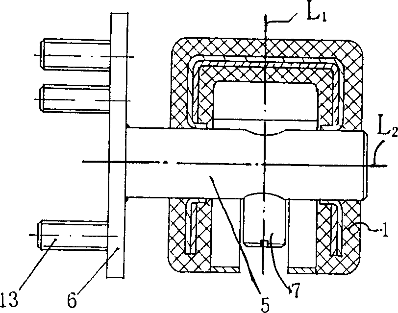
[0017] see Figure 1 ~ Figure 3 , The armrest body is composed of a fully sealed box-shaped steel framework 2 that can bear a plastic coating pressure of 9Mpa and a high-pressure engineering plastic cladding 3 with an injection molding pressure of 9Mpa covering the steel framework. There is a rotating handle installation groove 4 at the bottom of the front end of the handrail body. The support shaft 5 is contained in the afterbody of the armrest body and can rotate relatively with the armrest body. One end of the support shaft 5 protruding from the armrest body is fixed with a support shaft fixture 6 with a support shaft in a mounting hole. The axis line L1 of the limit screw 7 is perpendicular (or approximately) to the axis line L2 of the support shaft 5 and is threadedly fixed on the support shaft. A thrust nut 8 is fixed on the armrest body tail end relative to the limit screw extension, and the tail thread of the push rod 9 mounted on the armrest body passes through the ...
PUM
 Abstract
Description
Claims
Application Information
 - R&D
- Intellectual Property
- Life Sciences
- Materials
- Tech Scout
- Unparalleled Data Quality
- Higher Quality Content
- 60% Fewer Hallucinations
Browse by: Latest US Patents, China's latest patents, Technical Efficacy Thesaurus, Application Domain, Technology Topic, Popular Technical Reports.
© 2025 PatSnap. All rights reserved.Legal|Privacy policy|Modern Slavery Act Transparency Statement|Sitemap|About US| Contact US: help@patsnap.com


