Filter element

A filter element and filter medium technology, applied in the filter field, can solve the problems of automatic transmission failure, increased channel resistance, shortened product life, etc., and achieve the effects of preventing pressure loss, suppressing the increase of pressure loss, and preventing deformation

Inactive Publication Date: 2006-09-13
TOYO ROKI MFG CO LTD
View PDF2 Cites 7 Cited by
  • Summary
  • Abstract
  • Description
  • Claims
  • Application Information

AI Technical Summary

Problems solved by technology

[0006] On the other hand, this type of filter element tends to increase passage resistance due to the filter medium sticking phenomenon
Therefore, in the case where the liquid such as oil to be filtered has a low temperature, a desired flow rate of the liquid is not allowed to pass through, which leads to a disadvantage of shortening the life of the product
In addition, in the case where this filter element is used as an oil filter for an automatic transmission, the decrease in flow rate due to the increase in pressure loss may cause the automatic transmission to malfunction.

Method used


Image

  • Filter element
  • Filter element
  • Filter element

Examples


Embodiment Construction

[0019] Embodiments of the present invention will be described below with reference to the drawings.

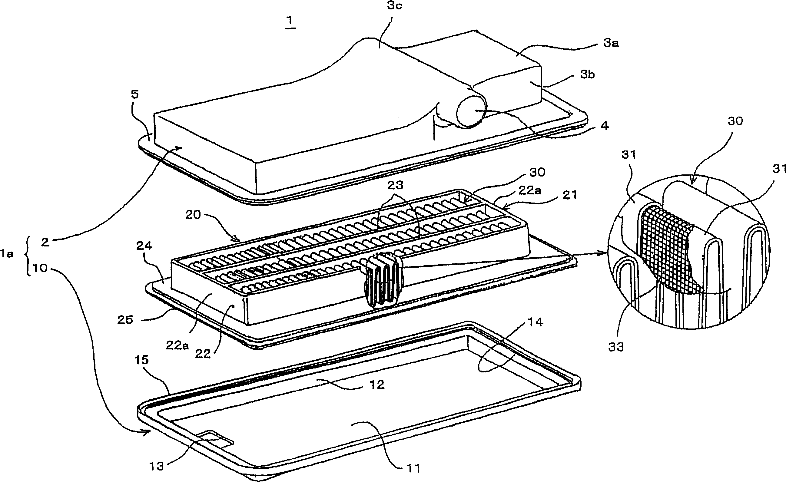
[0020] figure 1 A state is shown in which a filter element 20 according to an embodiment of the present invention is used for an oil filter 1 of an automatic transmission.

[0021] The oil filter 1 has a housing 1a forming its housing, in which a filter element 20 is accommodated. The housing 1 a is constituted by a lower case 10 having an opening 14 formed in an upper portion, and a cover 2 for closing the opening 14 of the lower case 10 .

[0022] The lower case 10 has a rectangular shape formed by a bottom surface 11 and a peripheral wall surface 12 surrounding the periphery of the bottom surface 11 . The bottom surface 11 is formed with an inflow port 13 which allows oil to flow into the housing 1a. At the upper end of the peripheral wall surface 12 forming the opening 14, a support flange 15 is formed on the entire peripheral edge and protrudes outward with a fixed dim...


PUM


Abstract

There is provided a filter element which maintains the flow rate of a fluid passing through a filter medium, restrains a pressure loss as far as possible, and is compact in size. In the filter element including a filter medium 30 pleated so that peaks 30a and valleys 30b are arranged alternately and a frame 21 for holding the filter medium 30, the frame 21 includes a frame body 22 forming the peripheral edge portion thereof and a plurality of ribs 23 extending in parallel on the inside of the frame body 22. The interval H between the ribs 23 is set at 5 to 35 mm, and the filter medium 30 is folded at an angle theta of at least four degrees at the peaks 30 a and the valleys 30 b.

Description

technical field [0001] The present invention relates to filters for fluid systems, and more particularly to filter elements for use in oil filters for automatic transmissions. Background technique [0002] Conventionally, in filters for liquid systems, such as oil filters for automatic transmissions, filter elements in which the filter media is pleated such that alternating peaks and The valley remains inside the frame. [0003] In general, filters have a problem of reducing pressure loss by controlling an increase in filtration efficiency and an increase in channel resistance. To solve this problem, different methods have been proposed in the past. In addition, in recent years, there has been a need to obtain a more compact filter while solving the above-mentioned problems. To meet this need, filter elements using pleated filter media are often used. Because of the pleating, such a filter element can have a larger filter area, making this type of filter element excellen...

Claims


Application Information

Patent Timeline
Patent Type & Authority Applications(China)
IPC IPC(8): F16H57/04B01D29/07
CPCB01D2201/12B01D29/07B01D2201/127F16H57/0404
Inventor 铃木兵升后藤雅则日尾阳介
Owner TOYO ROKI MFG CO LTD
Why Eureka
Try Eureka