Transmission method and process device of Ethernet service signal in wave division duplex network
A business signal, wavelength division multiplexing technology, applied in wavelength division multiplexing systems, multiplexing communications, data switching networks, etc. Simple network hierarchy and the effect of reducing transmission costs
- Summary
- Abstract
- Description
- Claims
- Application Information
AI Technical Summary
Problems solved by technology
Method used
Image
Examples
Embodiment 1
[0065] Embodiment 1. Realizing GE channel multicast in WDM network
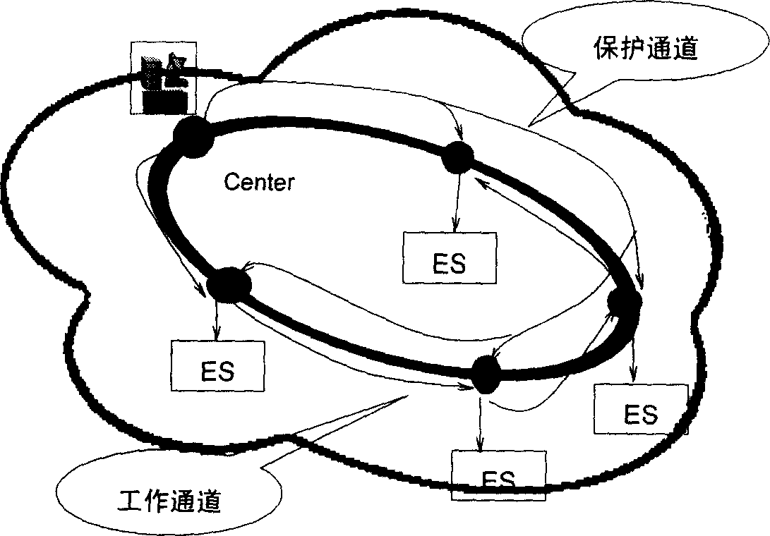
[0066] Multicast of large-grained GE services is realized based on GE ADM (space division crossover) technology. Using this technology, GE services from the central source site are multicast to downstream edge sites through the GE pipeline provided by the WDM system. At the same time, based on GE The cross-connection realizes the downlink, replication, and continuous transmission of GE services to downstream sites.
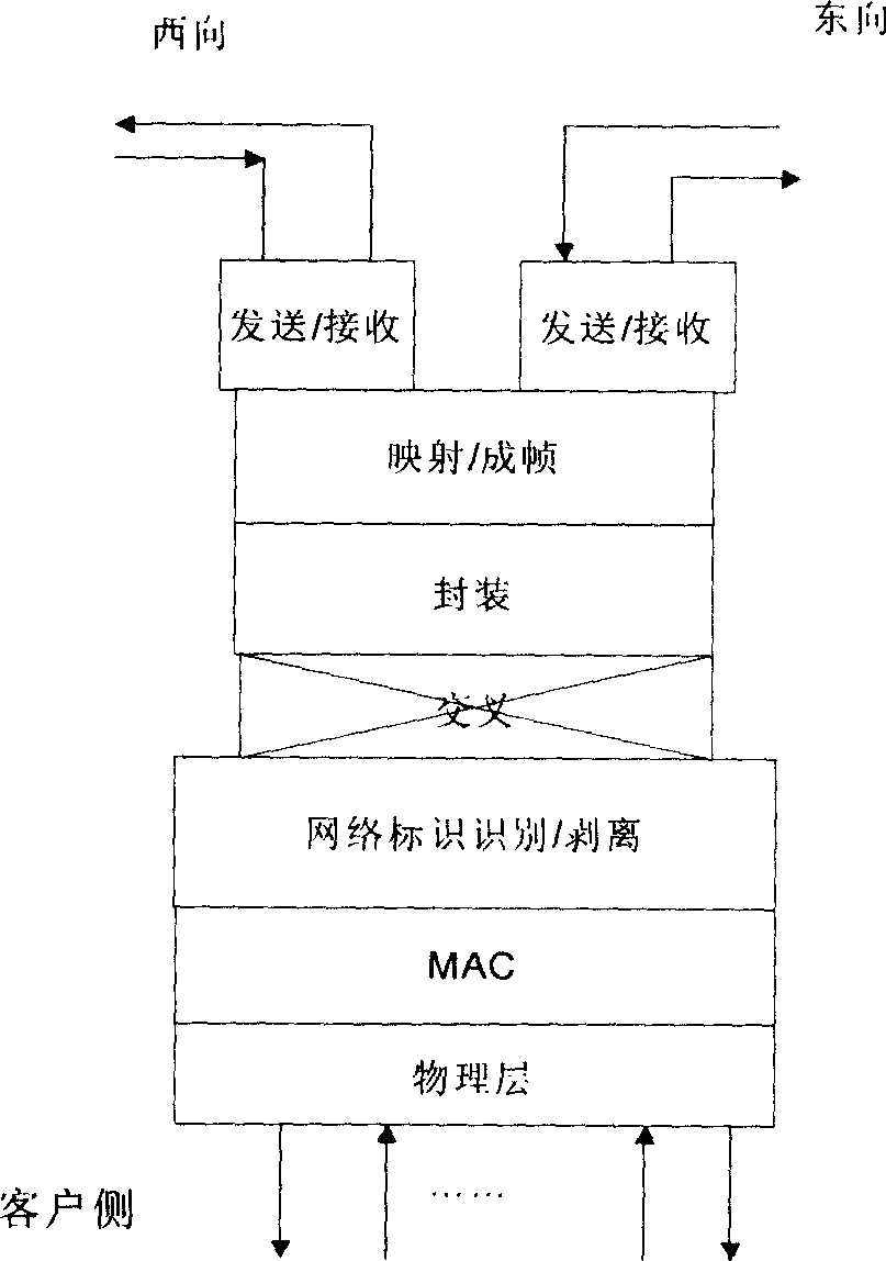
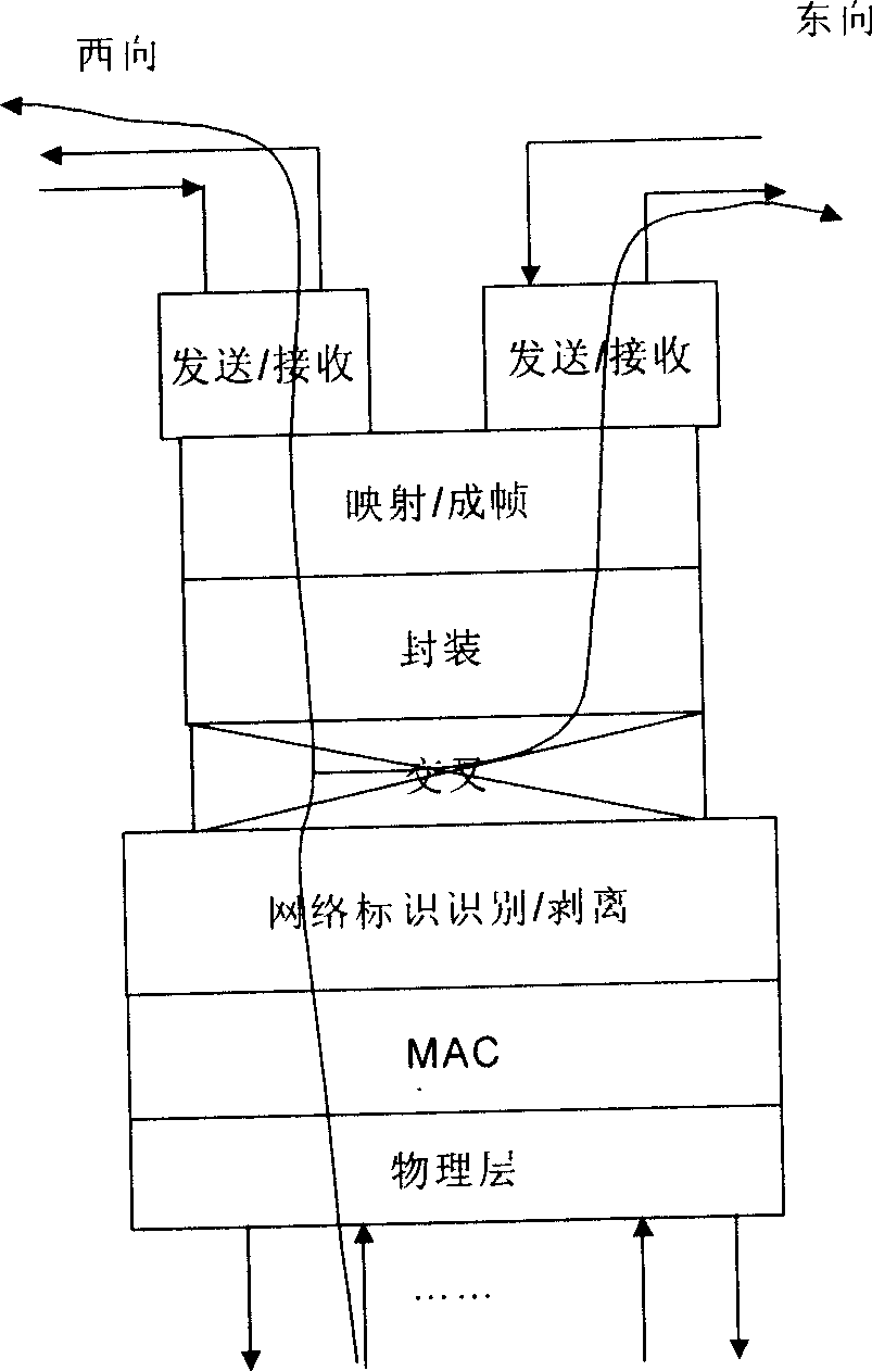
[0067] The service sending side, such as image 3 As shown, at the source site, the service sent by the client side enters the WDM system through the physical layer interface. The GE service in Embodiment 1 only requires the multicast of the GE channel, so the MAC layer and the WDM network identification module do not need to process the service , in the GE ADM cross-connect module, using the cross-connect function, GE services can be output through the west optical interface or the east optical...
Embodiment 2
[0072] Embodiment 2: Realize service multicast in WDM network based on the MAC layer label carried by the service
[0073] MAC layer labels include VLAN labels, MPLS labels, or RPR labels. It is most convenient to use VLAN labels. The following uses VLAN labels as an example to describe in detail.
[0074] When the uplink services at the central source site include different VLAN tags in the GE services, in order to improve bandwidth utilization, the WDM network multicasts them to different downstream edge sites through shared channels based on the VLAN tags.
[0075] The functions implemented by the central source site in this embodiment are the same as those in Embodiment 1, and the specific implementation process is as follows Figure 4 As shown, the GE services coming from the source site are services with different VLAN tags. The selection of east-west services and the replication of services are the same as those in Embodiment 1. The difference is that the MAC layer of t...
Embodiment 3
[0078] Embodiment 3: Based on the self-defined identification of the WDM network, the multicast of services in the shared channel is realized
[0079] Also to improve bandwidth utilization, a set of identification information for each site and port can be customized in the WDM network to distinguish the Ethernet service signals sent to different sites at the same time through the shared Ethernet channel.
[0080] Such as Figure 8 As shown, 4 GEs come from the central source site and share a channel for transmission in the WDM system. These 4 GEs need to be multicast to different sites. At this time, the source site needs to control the bandwidth of the service based on VLAN at the MAC layer, and control the bandwidth of the WDM line within the predetermined capacity. Since multiple GEs share one or several channels, such as sharing a GE channel, then In order to distinguish the upstream services of different ports in this shared channel and the receiving site to distinguish ...
PUM
 Abstract
Description
Claims
Application Information
 - R&D
- Intellectual Property
- Life Sciences
- Materials
- Tech Scout
- Unparalleled Data Quality
- Higher Quality Content
- 60% Fewer Hallucinations
Browse by: Latest US Patents, China's latest patents, Technical Efficacy Thesaurus, Application Domain, Technology Topic, Popular Technical Reports.
© 2025 PatSnap. All rights reserved.Legal|Privacy policy|Modern Slavery Act Transparency Statement|Sitemap|About US| Contact US: help@patsnap.com


