Pipeline type steam purger

A purging device and pipeline-type technology, applied in the field of fluid transmission, can solve the problems of short life, easy fire and explosion, rot, etc., and achieve the effect of long life, safe use, and non-perishable

Inactive Publication Date: 2006-09-20
李小磊
View PDF0 Cites 4 Cited by
  • Summary
  • Abstract
  • Description
  • Claims
  • Application Information

AI Technical Summary

Problems solved by technology

[0002] At present, the cleaning of oil tanker tanks in our country is carried out by blowing hot steam at 160°C into the tank through a rubber hose. During the process of blowing hot steam, the rubber hose will violently swing inside and outside the tank and generate a lot of Static electricity, when the oil and gas inside or outside the tank are in the explosion range, it is very easy to cause fire and explosion
In addition, the life of the rubber hose is very short at a high temperature of 160°C, and it will rot in about 3 weeks

Method used


Image

  • Pipeline type steam purger

Examples


Embodiment Construction

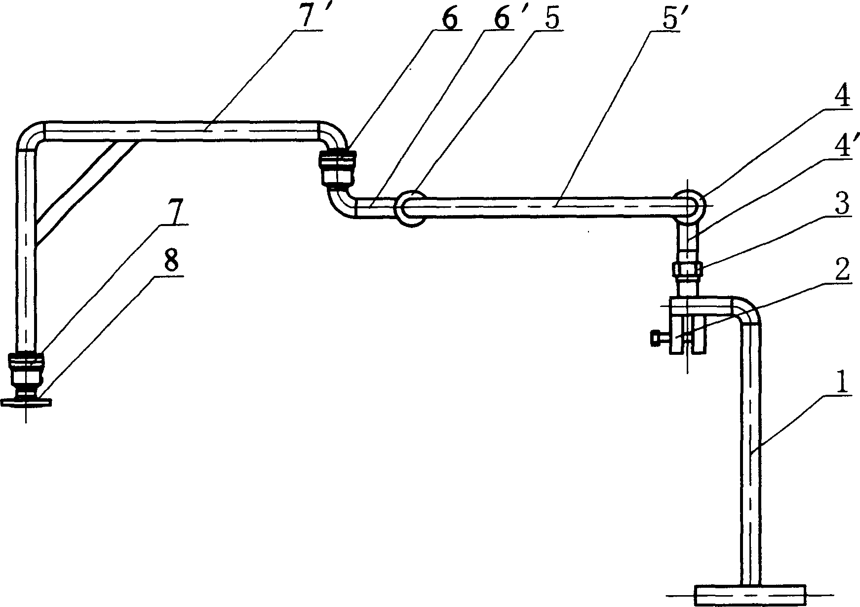
[0007] Such as figure 1 As shown, the device is divided into two parts, the movable metal pipe and the steam purge pipe, consisting of the rotary joints 4, 5, 6, 7 and the corresponding metal pipes 4', 5', 6', 7' such as figure 1 The sequence shown is connected with each other to form a movable metal pipe. According to the actual situation, there may be one or more rotary joints. The steam purge pipe is composed of a metal pipe 1 with a horizontal pipe and a tank clip 2 fixed on the metal pipe. One end of the movable metal pipe is connected to the steam purge pipe by a pipe connection joint 3 . The other end of the movable metal pipe is connected with the high neck flange 8 . When in use, first connect the high-neck flange 8 to the steam supply pipeline, then insert the steam purge pipe vertically into the tank, and fix its upper end at the tank mouth with a tank card, and then use the pipe connection joint to connect the movable After the metal pipe is connected to the uppe...


PUM


Abstract

A pipeline-type steam scavenger for washing the oil tank of tank truck is characterized by that a movable metallic pipe with rotary jointer is connected via pine jointer to a steam scavenging pipe. Its advantages are no generation of static electricity and long service life.

Description

technical field [0001] The invention relates to a steam purging device, which belongs to the field of fluid transmission. technical background [0002] At present, the cleaning of oil tanker tanks in our country is carried out by blowing hot steam at 160°C into the tank through a rubber hose. During the process of blowing hot steam, the rubber hose will violently swing inside and outside the tank and generate a lot of Static electricity, when the oil and gas inside or outside the tank are in the explosion range, it is very easy to catch fire and explode. In addition, the life of the rubber hose is very short at a high temperature of 160°C, and it will rot in about 3 weeks. Contents of the invention [0003] The purpose of the present invention is to provide a pipeline type steam purging device, which can blow 160°C hot steam into the tank without swinging, without generating static electricity, and has a long service life at the same time. [0004] The technical scheme a...

Claims


Application Information

Patent Timeline
Patent Type & Authority Applications(China)
IPC IPC(8): B08B3/00
Inventor 李小磊
Owner 李小磊
Why Eureka
Try Eureka