Vacuum cleaner and method for mounting the supported arch member on the shell of the vacuum cleaner

A technology of vacuum cleaners and bows, which is applied in the direction of vacuum cleaners, handles, cleaning equipment, etc., can solve the problems of large number of parts and complex structures, etc., and achieve manufacturing cost reduction, reliable axial and/or radial, reliable and safe locking Effect

Inactive Publication Date: 2010-05-26
BSH BOSCH & SIEMENS HAUSGERAETE GMBH
View PDF3 Cites 0 Cited by
  • Summary
  • Abstract
  • Description
  • Claims
  • Application Information

AI Technical Summary

Problems solved by technology

But the downside: the construction there is complex and the number of parts is high

Method used


Image

  • Vacuum cleaner and method for mounting the supported arch member on the shell of the vacuum cleaner
  • Vacuum cleaner and method for mounting the supported arch member on the shell of the vacuum cleaner
  • Vacuum cleaner and method for mounting the supported arch member on the shell of the vacuum cleaner

Examples


Embodiment Construction

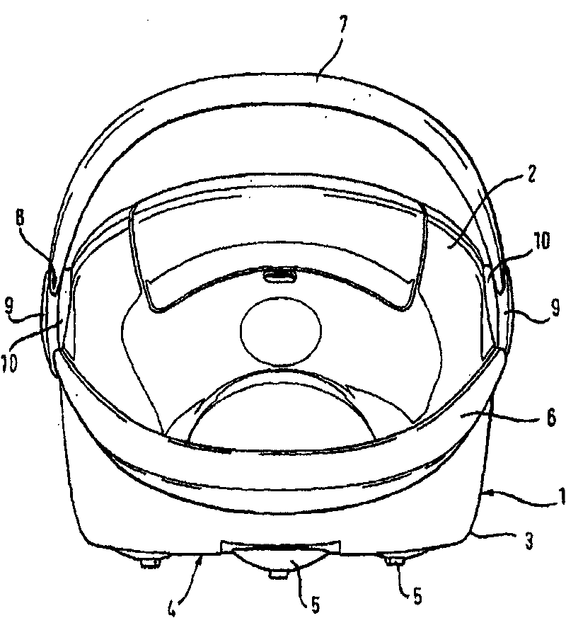
[0041] figure 1 An embodiment of a vacuum cleaner according to the invention is shown. The vacuum cleaner has a multi-part housing 1 in which the functional components of the vacuum cleaner are arranged, but not shown. The first housing part 2 forms an upper housing which is mounted on a second housing part 3 which forms a lower housing. On an outer bottom side 4 of the housing part 3 , movable rollers 5 are supported, which are rotatable and pivotable. The housing part 3 has a rigidly fixed locking handle 6 . In addition to the locking handle 6, an additional support bracket 7 is provided. The support bracket 7 is pivotably connected to the first housing part 2 by means of two pivot bearings 8 arranged opposite one another. Support bow 7 from the figure 1 The side of the vacuum cleaner shown on the left extends to the opposite figure 1 The side of the vacuum cleaner shown on the right. The support bow 7 is U-shaped, extends above the cleaner at a distance from the f...


PUM


Abstract

The invention relates to a vacuum cleaner comprising a housing and a carrying arched element mounted in a manner that, by means of at least one pivot bearing, which has a first pivot bearing part anda second pivot bearing part that can rotate relative to the first pivot bearing part about a common rotation axis, enables it to pivot relative to the housing between two end positions of an operational pivot angle. The aim of the invention is to create a vacuum cleaner whereby a carrying arched element that can pivot relative to the housing between two end positions of an operational pivot angleis securely mounted in an simple manner. To this end, the pivot bearing is designed for joining or separating the first pivot bearing part to or from the second pivot bearing part in a mounting angular position located outside of the operational pivot angle. This enables the pivot bearing parts of the pivot bearing to be mounted and detached solely in a mounting angular position. The pivot bearingparts cannot be detached when the carrying arched element is located in an operational pivot angle. This makes it possible to eliminate separate parts that would otherwise be necessary for preventingan unwanted detaching of the carrying arched element from the vacuum cleaner.

Description

technical field [0001] The invention relates to a vacuum cleaner and to a method for mounting a support bracket on a housing part of a vacuum cleaner. Background technique [0002] A similar vacuum cleaner is known from DE-AS 12 89 628, in which the support bracket is pivotally mounted in a groove of a disk concentric with its axis of rotation. An end of the support bracket which is bent around the tube is provided with a stop. The groove partially extends as far as the outer edge of the disk, so that two stops are formed between which the support bracket can freely pivot relative to the disk. With this solution, the support bracket can be pivoted relative to the housing between two end positions of the operating pivot angle. But the downside: the construction there is complex and the number of parts is high. Contents of the invention [0003] The object of the present invention is to propose a vacuum cleaner in which a support bracket that is pivotable relative to the ...

Claims


Application Information

Patent Timeline
Patent Type & Authority Patents(China)
IPC IPC(8): A47L9/32
CPCA47L9/327
Inventor S·哈姆R·伊利希A·克莱因亨茨
Owner BSH BOSCH & SIEMENS HAUSGERAETE GMBH
Why Eureka
Try Eureka