Method and apparatus for repeating a signal in a wireless communication system

a wireless communication system and signal repeating technology, applied in repeater circuits, line-transmission details, instruments, etc., can solve the problems of frequency selective fading, limited gain of frequency domain coding and scheduling, and the inability to optimize system parameters for all users in a cell

Inactive Publication Date: 2012-11-27
TELEFON AB LM ERICSSON (PUBL)
View PDF43 Cites 15 Cited by
  • Summary
  • Abstract
  • Description
  • Claims
  • Application Information

AI Technical Summary

Benefits of technology

[0025]The inventive solution achieves the object stated above by enabling the diversity of the system to be controlled. In particular, the diversity in different parts of one cell can be controlled independently of each other. This enables the creation of optimal time and frequency selectivity in different parts of the cell. This is particularly useful when indoor scenarios should be covered by outdoor base stations.
[0030]If a communications link between the repeater and the system is used, the repeater can measure certain channel parameters and feed them back to the system. In this case, the repeater may also comprise a measuring unit for measuring parameters related to the downlink signal and transmission means for transmitting said parameters to the base station. The system can then respond with optimal settings on the adjustable parameters in the repeater, such as time delay, frequency shift and phase rotation angle, that is, parameters that can be changed between different transmit branches. In this way it is possible to adapt the delay and / or phase rotation in the repeater node to the current traffic load and other parameters at any given time.

Problems solved by technology

Frequency selective fading is encountered in scenarios where a large delay spread is present.
Hence, the gain of frequency domain coding and scheduling is limited in an indoor scenario.
Also, since the requirements from different areas of a cell may be very different, it may be impossible to optimize system parameters for all users in a cell.
In particular the requirements from outdoor and indoor users will typically be very difficult.
Similar problems may arise if a cell covers an outdoor cell comprising areas with very different topographies.

Method used


Image

  • Method and apparatus for repeating a signal in a wireless communication system
  • Method and apparatus for repeating a signal in a wireless communication system
  • Method and apparatus for repeating a signal in a wireless communication system

Examples


Embodiment Construction

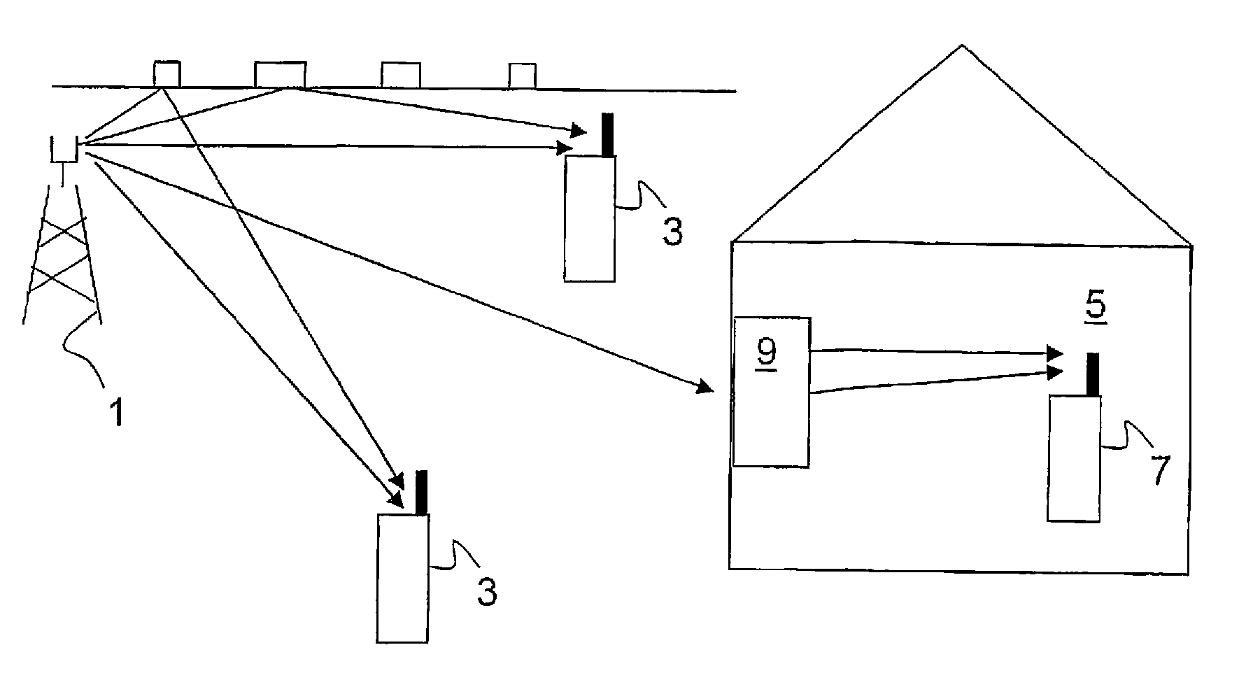
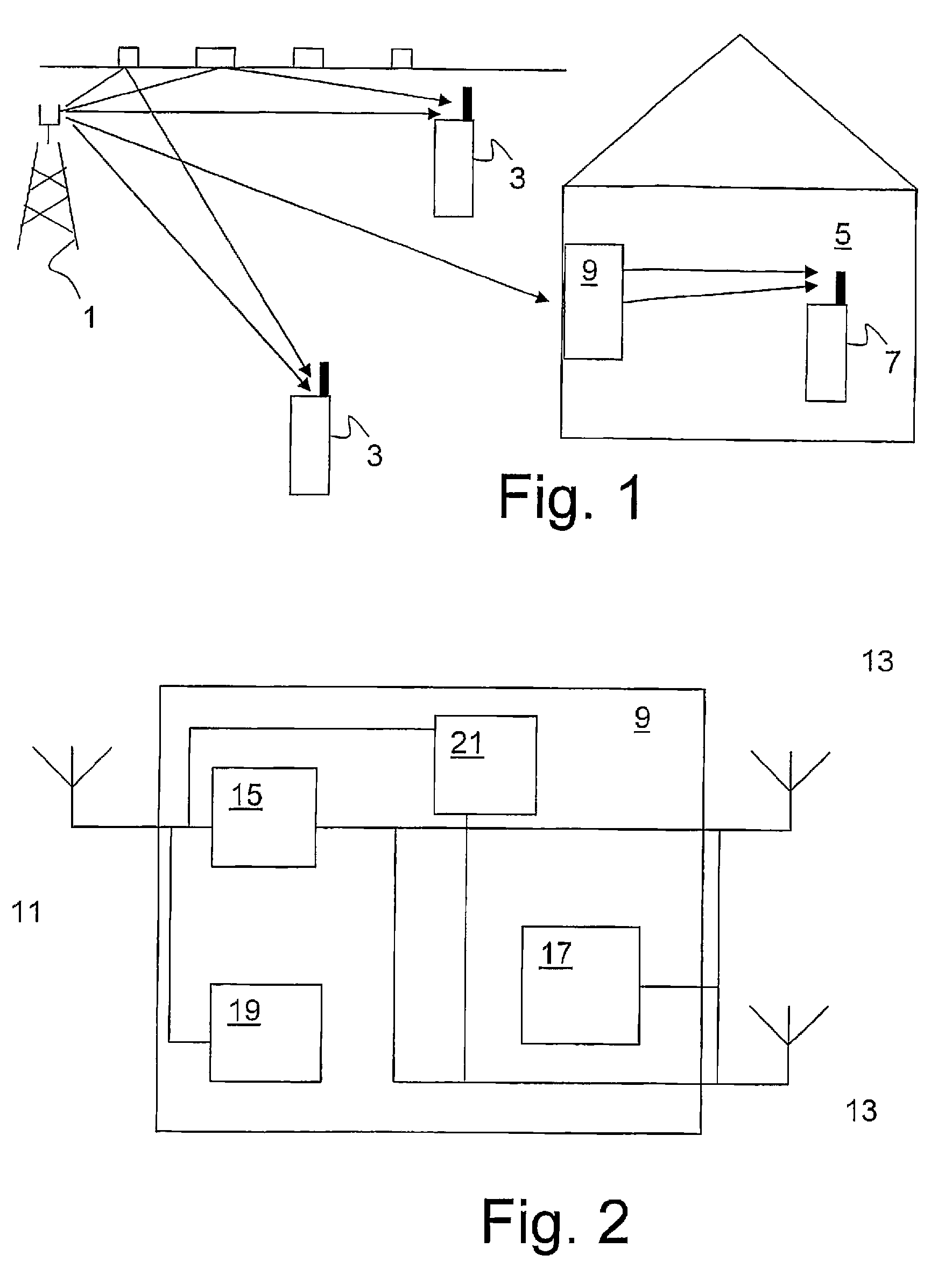
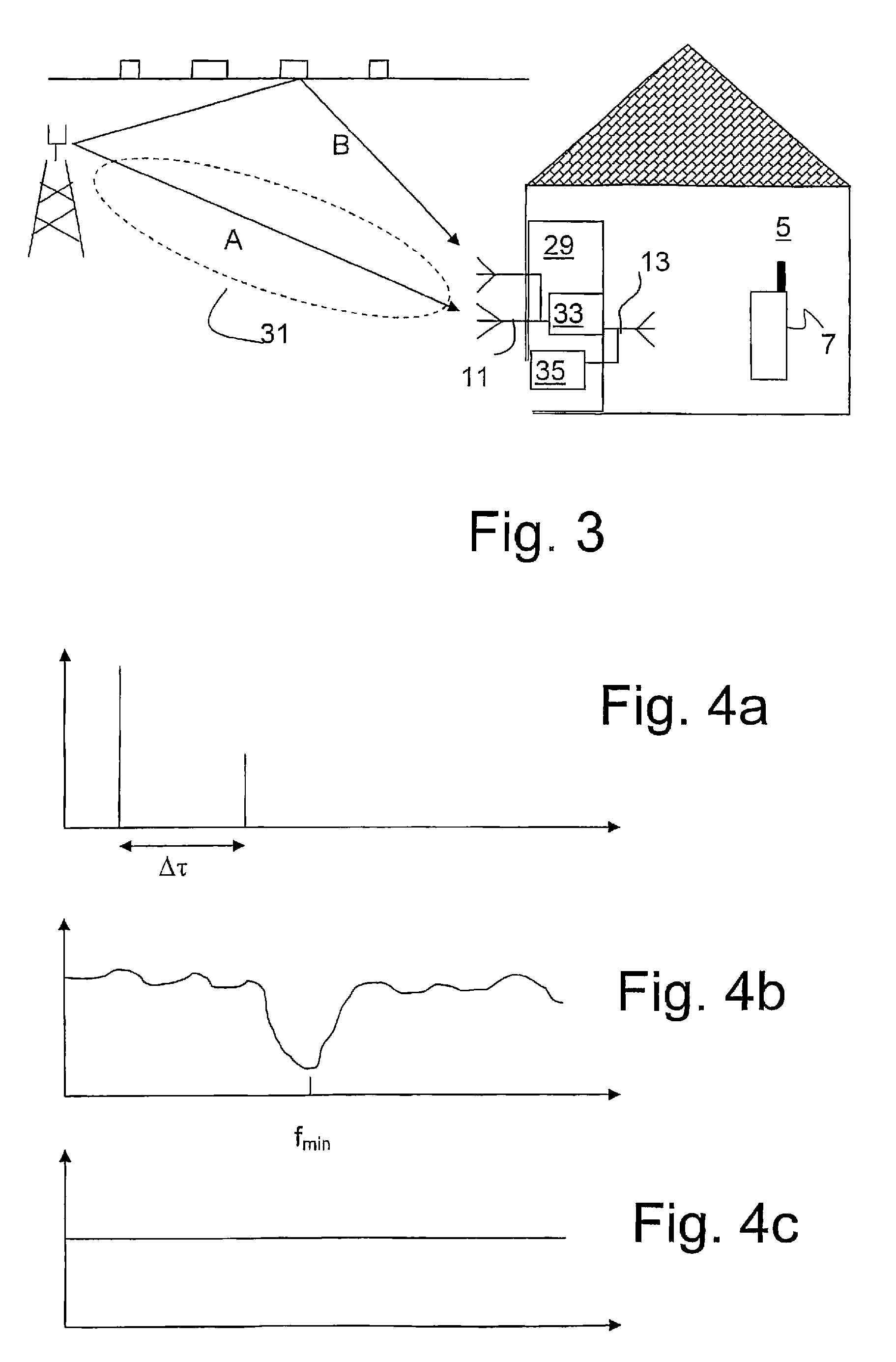
[0038]FIG. 1 shows a network in which the method and apparatus according to the invention can be applied advantageously. In a cellular network a base station 1 is located outdoors. The base station 1 communicates over the radio interface with a number of user terminals 3 located outdoors in the base station's 1 cell. For each of these user terminals 3, reflections from the surroundings ensure diversity in that each terminal 3 receives the same signal through several paths, typically a direct path from the base station 1 and one or more paths including reflections from buildings or other structures located between the base station 1 and the user terminal 3. This provides for a diversity gain.

[0039]In the base station's 1 cell there is also a building 5 in which a user terminal 7 is located. Because of the attenuation in the wall of the building 5 a repeater 9 is placed on the wall to amplify the signal for the benefit of the user terminal 7 inside the building. According to the inven...


PUM


Abstract

The invention relates to communication in a wireless communications network in which a cell comprises areas with different topographies, for example between indoor and outdoor areas. The communication is optimized by means of a repeater for use in a fixed wireless broadband communications system, comprising receiving means for receiving a downlink signal from a base station, signal processing means for processing the downlink signal to produce an output signal, and transmitting means for transmitting the output signal, said repeater being characterized in that it comprises means for creating diversity in the output signal.

Description

TECHNICAL FIELD[0001]The present invention relates to a repeater for use in a wireless communications system as defined in the preamble of claim 1, to communication methods as defined in the preambles of claims 10 and 20, respectively, and to a wireless communication system as defined in the preamble of claim 18.BACKGROUND AND PRIOR ART[0002]Repeaters are a cost-efficient way to increase the coverage in a wireless communications system. Several repeater nodes can be placed within the coverage range of a particular base station. The repeater nodes extend the effective coverage of the base station, that is, the size of the cell, by retransmitting the signal received from the base station.[0003]Repeaters are sometimes used to provide indoor coverage from an outdoor base station. The attenuation in walls is in the order of 10-20 dB, which means that without a repeater the signal strength experienced by indoor terminals may be very small. A simple repeater may be used to amplify the sign...

Claims


Application Information

Patent Timeline
Patent Type & Authority Patents(United States)
IPC IPC(8): H04B7/14
CPCH04B7/15542H04B7/155H04B7/2606
Inventor GORANSSON, BOANDERSSON, MATS H.
Owner TELEFON AB LM ERICSSON (PUBL)
Why Eureka
Try Eureka