Valve, especially proportional pressure control valve

a valve body technology, applied in the field of valves, can solve the problems of valve and relevant parts of the hydraulic system failure, especially harmful problems, and poor stability of the conventional proportional pressure control valve, and achieve the effect of reducing the diversity of components and good stability

Inactive Publication Date: 2010-11-30
HYDAC FLUITECHNIK GMBH
View PDF21 Cites 18 Cited by
  • Summary
  • Abstract
  • Description
  • Claims
  • Application Information

AI Technical Summary

Benefits of technology

[0006]An object of the present invention is to provide a valve, especially a proportional pressure control valve, which has good stability when thin-liquid fluid media are used, and which especially when used in safety-relevant domains including hydraulic drive unit helps reduce the diversity of components.

Problems solved by technology

These conventional proportional pressure control valves have poor stability especially for thin-liquid fluid media, i.e., they begin to “oscillate”.
This problem is especially harmful when the known valves are designed to perform special functions, for example, in motor vehicle power steering systems, hydraulic drive units, and other safety engineering-relevant domains.
The instabilities occurring can lead to failure of the valve and the pertinent parts of a hydraulic system.
This functional structure is reliable in operation, but due to the plurality of valves its failure in operation must be expected.
This failure shortens maintenance intervals.
The known solution also requires a large amount of installation space and is expensive to manufacture due to the diversity of parts.

Method used


Image

  • Valve, especially proportional pressure control valve
  • Valve, especially proportional pressure control valve
  • Valve, especially proportional pressure control valve

Examples


Embodiment Construction

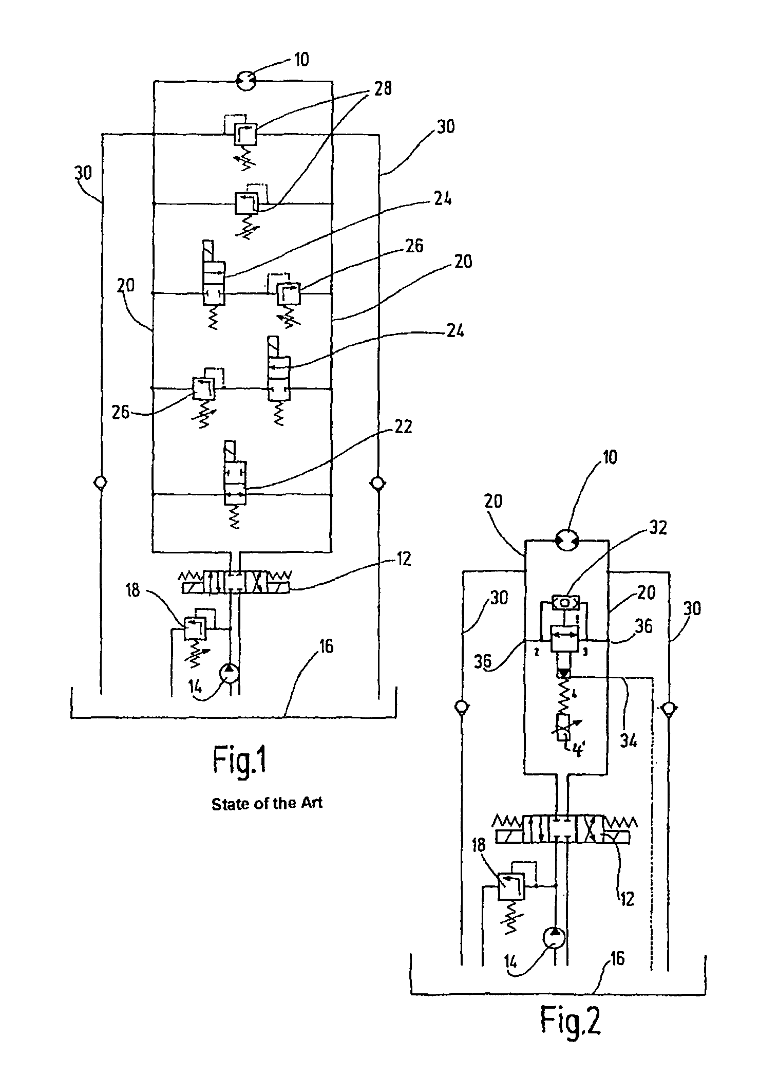
[0013]FIG. 1 is a circuit diagram part of a hydraulic drive unit for a scissors lift platform. These vehicles generally have two axles. Generally a rear drive is implemented, and the front axle can be separately actuated for implementation of optional all-wheel drive. The drives for the two axles are designed to be essentially the same. FIG. 1 for the prior art shows a hydraulic motor 10 as the driving means for the axle of the pertinent vehicle, which axle is not detailed. Depending on the operating position of the 4 / 3-way valve 12 in both directions of rotation, the motor can be driven in both directions of rotation for forward or backward operation and for implementing a braking function. The 4 / 3-way valve 12 according to FIG. 1 is shown in the neutral position, and otherwise is connected on the input side to the hydraulic pump 14 and to a tank 16.

[0014]The supply line of the hydraulic pump 14 is safeguarded via a conventional pressure control valve 18. Two parallel running suppl...


PUM


Abstract

A proportional pressure control valve includes a valve housing (38) with at least three fluid connections (1, 2, 3). The valve can be connected to a hydraulic drive system with a pre-determinable consumer pressure. The valve can perform reliable valve switching functions even for low-viscous fluid media, and can reduce its susceptibility to disturbance variables. A valve piston (56) actively connected to a pilot seat (5) by an energy accumulator (62) can be controlled by a control device (40). The consumer pressure on a fluid connection (1) acts on the valve piston (56) such that, according to the consumer pressure and the actuating force of the control device (40), a fluid can flow between the two other fluid connections (2 and 3) in both directions inside the valve housing (38).

Description

FIELD OF THE INVENTION[0001]The present invention relates to a valve, especially a proportional pressure control valve, including a valve housing with at least three fluid ports. The valve is connectable to a hydraulic drive system with a definable consumer pressure.BACKGROUND OF THE INVENTION[0002]Proportional pressure control valves (such as disclosed in U.S. Pat. No. 4,316,599) are known which among other things form control valves for oil hydraulic systems and deliver an essentially constant output pressure for a variable input pressure. The output pressure to be controlled is dictated by the current signal delivered by the corresponding trigger electronics and acting on the actuating magnet as the magnet system. The actuating magnet can be made as a pressure-tight oil bath magnet and has a long service life.[0003]Proportional pressure control valves such as these can be directly controlled piston sliding valves in a three-way design, i.e., with output side pressure safeguarding...

Claims


Application Information

Patent Timeline
Patent Type & Authority Patents(United States)
IPC IPC(8): F16K11/07
CPCF15B13/024F15B13/0433F16H61/4043F16H61/4148F16K17/0473F16K17/105F16K17/22G05D16/166G05D16/2093G05D16/101G05D16/2024G05D16/2097Y10T137/7771Y10T137/86614Y10T137/86702Y10T137/87917F15B13/044
Inventor BRUCK, PETERALBERT, HERMANN
Owner HYDAC FLUITECHNIK GMBH
Why Eureka
Try Eureka