Method and device for friction stir welding

A friction stirring and joining method technology, applied in welding equipment, metal processing equipment, manufacturing tools, etc., can solve the problems of tool length elongation, needle thermal expansion, small spacing, etc., to ensure the effect of joint strength

Inactive Publication Date: 2006-09-27
TOYOTA JIDOSHA KK
View PDF1 Cites 4 Cited by
  • Summary
  • Abstract
  • Description
  • Claims
  • Application Information

AI Technical Summary

Problems solved by technology

[0003] However, when friction stir welding is performed continuously, the needle portion may thermally expand due to frictional heat between the member to be joined and the needle portion at the tip of the tool, and the tool length may elongate.
Therefore, when friction stir welding is continuously performed using the friction stir welding apparatus described in Patent Document 1, there is a problem that the actual distance between the receiving member and the needle portion becomes smaller than that stored in the control device during teaching. The distance between the receiving part and the needle part in the medium is small, and holes are generated in the friction stir joint part, and the joint strength required by the product cannot be obtained.

Method used


Image

  • Method and device for friction stir welding
  • Method and device for friction stir welding
  • Method and device for friction stir welding

Examples


Embodiment Construction

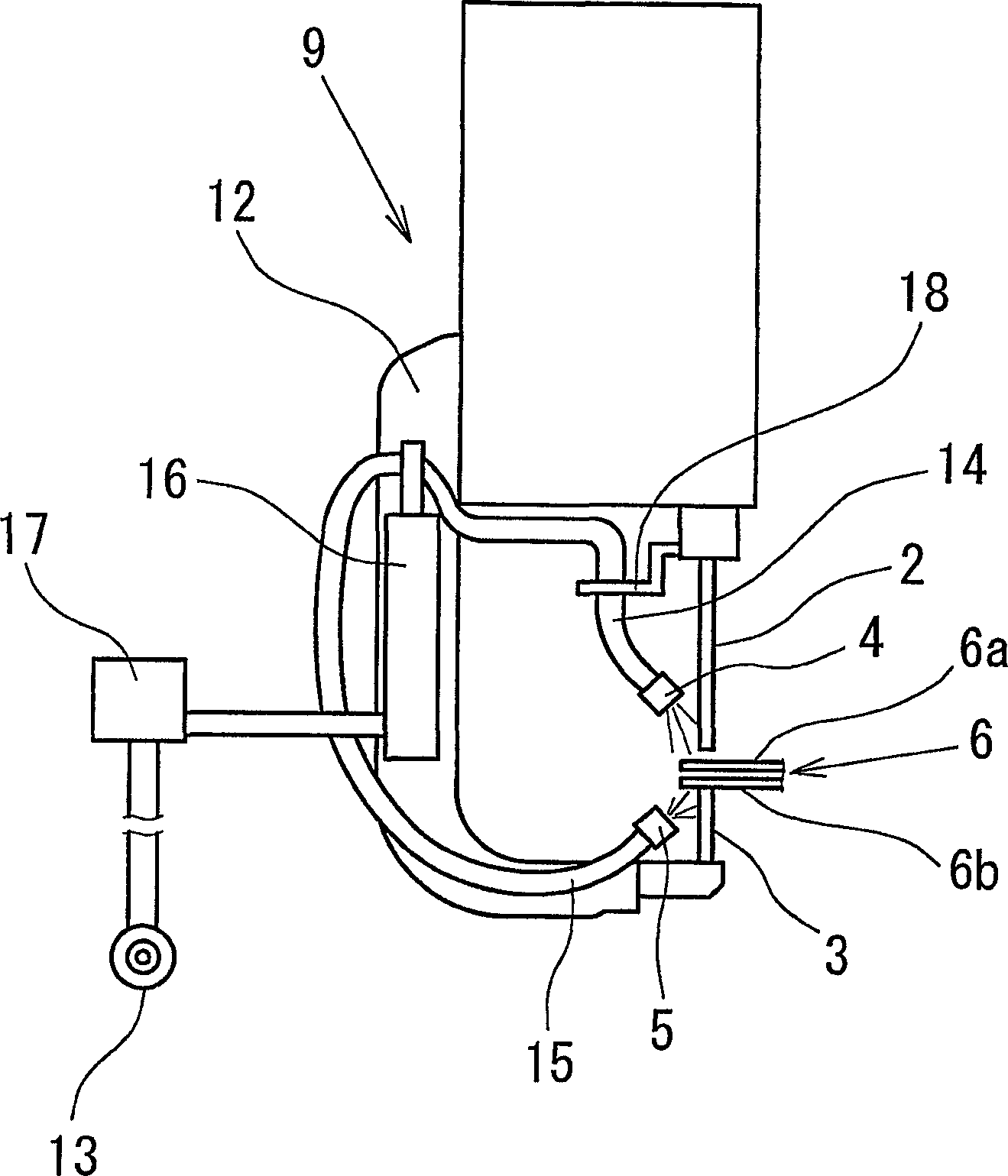
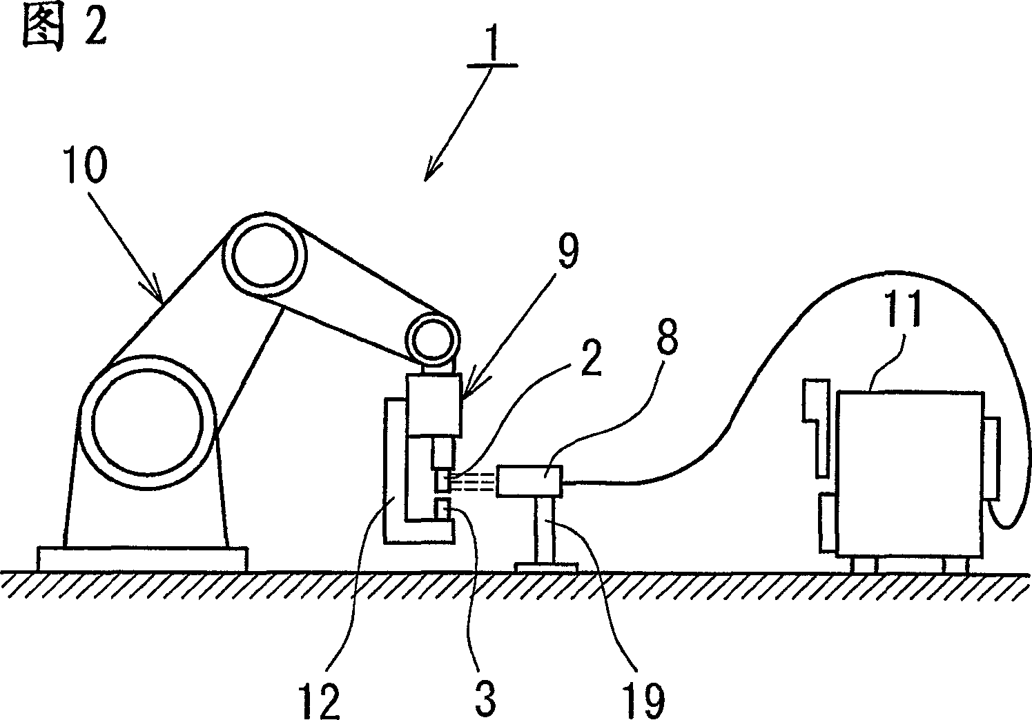
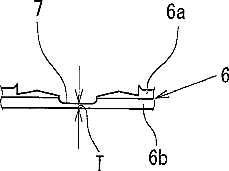
[0039] will be combined below Figure 1-5 An example of the present invention will be described. Such as figure 1 As shown, the friction stir welding apparatus 1 cools the upper tool 2 and the lower tool 3 by the air injected from the respective air nozzles 4, 5, and resists the friction caused by the rotating upper tool 2 and the workpiece 6 (parts to be joined 6a, 6b). The thermal expansion of each tool 2, 3 caused by heat is suppressed. Therefore, this friction stir welding device 1 is configured to properly maintain the gap G between the upper tool 2 and the lower tool 3 during friction stir welding, as image 3 As shown, forming the friction stir welded portion 7 having an appropriate thickness of the remaining mother plate thickness T between the overlapped workpieces 6 ensures the joint strength of the friction stir welded portion 7 . Furthermore, as shown in FIG. 2 , the friction stir welding device 1 is equipped with a non-contact temperature sensor 8 (tool tempera...


PUM


Abstract

A method and a device for friction sir welding capable of achieving sufficient welding strength of a product. [MEANS FOR SOLVING PROBLEMS] Thermal expansion of each tool (2, 3) is prevented because each tool (2, 3) is cooled by air jetted from each air nozzle (4, 5), and this appropriately maintains a gap between an upper tool (2) and a lower tool (3). As a result, a friction stir-welded portion having a residual base plate thickness with an appropriate thickness between an outer panel (6a) and an inner panel (6b) is formed, achieving sufficient welding strength of an engine hood. Air cooled by an extreme low temperature air producer (16) is jetted from each air nozzle (4, 5) to cool each tool (2, 3), and each tool (2, 3) is effectively cooled. The structure above enables thermal expansion of each tool (2, 3) to be constrained to a minimum level to produce a friction stir-welded portion with a residual base plate thickness having a more stable thickness, and as a result, welding strength of the engine hood is sufficiently achieved.

Description

technical field [0001] The present invention relates to a friction stir welding method and a friction stir welding apparatus used for joining aluminum materials or the like. Background technique [0002] In friction stir welding (welding), the joined parts to be joined to each other are overlapped, a rotating tool is approached from the overlapping direction of the joined parts and pressed into the overlapped joined parts, and the joined parts and the tool The frictional heat of the pin portion at the tip softens the joined member around the tool, and the softened joined member is stirred by the rotating pin. Thus, a friction stir welded portion having a thickness (hereinafter simply referred to as an excess thickness) in the overlapping direction of the joined members is formed between the overlapped joined members that are joined. It is known that in such friction stir welding, the needle portion of the tool penetrates the overlapped joined members, a hole is formed in th...

Claims


Application Information

Patent Timeline
IPC IPC(8): B23K20/12
CPCB23K20/1235B23K20/1265
Inventor 小塚裕铃木实野村浩二藤泽泰成内田圭亮池田贵史森尊治
Owner TOYOTA JIDOSHA KK
Why Eureka
Try Eureka