Cladding material and casing for electronic devices

一种电子设备、包层的技术,应用在电子设备用壳体领域,能够解决层易剥离等问题,达到确保接合强度、抑制比重变大的效果

Active Publication Date: 2017-09-26
PROTERIAL LTD
View PDF2 Cites 3 Cited by
  • Summary
  • Abstract
  • Description
  • Claims
  • Application Information

AI Technical Summary

Problems solved by technology

[0003] However, when a clad material is produced by directly joining a layer composed of a Mg-based alloy and a layer composed of an Al-based alloy, a fragile intermetallic compound is precipitated at the bonding interface between the layers, and as a result, a gap between the layers may occur. The problem of easy separation between

Method used


Image

  • Cladding material and casing for electronic devices
  • Cladding material and casing for electronic devices
  • Cladding material and casing for electronic devices

Examples


no. 1 Embodiment approach

[0047]

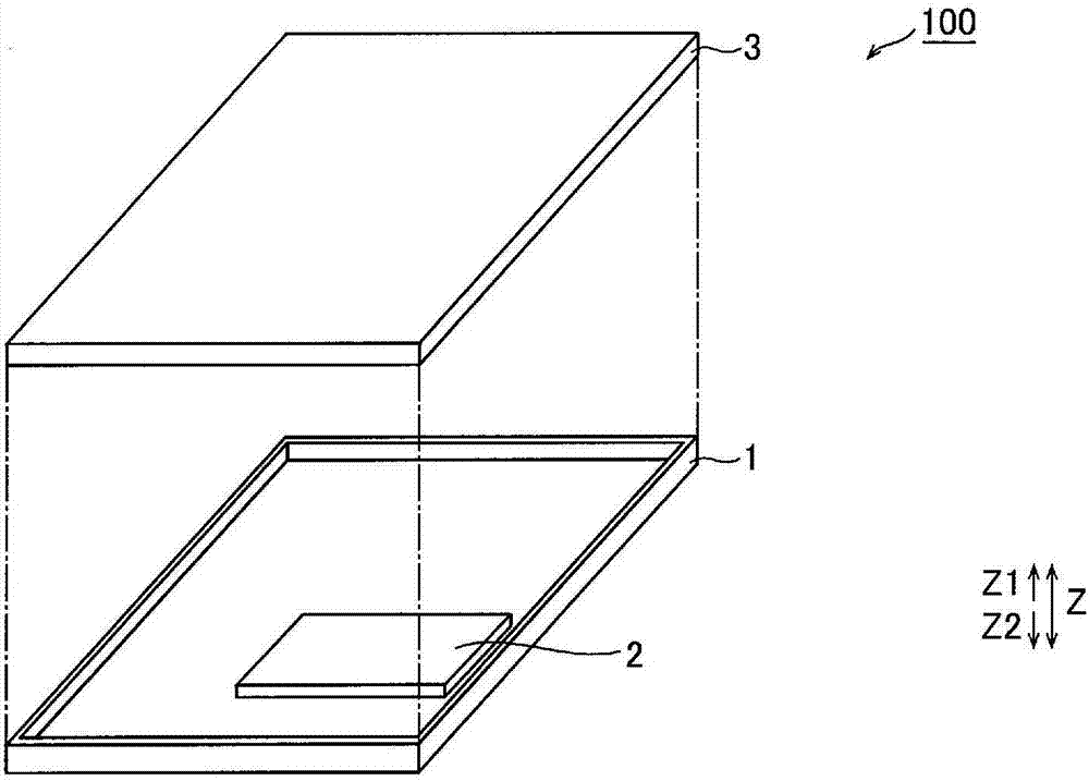
[0048] First, refer to figure 1 and figure 2 , the configuration of the electronic device 100 in the first embodiment of the present invention will be described.

[0049] The electronic device 100 in the first embodiment of the present invention is, for example, a portable electronic device. This electronic device 100 includes a box-shaped case 1 used as a structural member of the electronic device 100 , a substrate 2 disposed on the case 1 , and a display unit 3 bonded to the substrate 2 to display an image or the like. Among them, the case 1 is an example of the "case for an electronic device" in the scope of the claims.

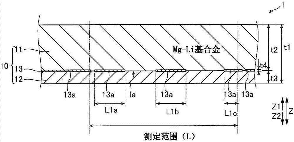
[0050] (composition of cladding material)

[0051] Case 1 as figure 2 Consists of cladding material 10 as shown. Specifically, the case 1 is composed of a cladding material 10 including a Mg—Li layer 11 , an Al layer 12 , and a joint portion 13 . In addition, the cladding material 10 is bonded in a state where the Mg—Li layer 11 and the ...

no. 2 Embodiment approach

[0081] Next, refer to Figure 4 , and the second embodiment of the present invention will be described. In the second embodiment, a case where the cladding material 210 has a five-layer structure will be described.

[0082]

[0083] In the second embodiment, the cladding material 210 has an Al layer 214 and a bonding portion 215 in addition to the Mg—Li layer 211 , the Al layer 212 , and the bonding portion 213 . In addition, in the clad material 210 , the Al layer 214 , the Mg—Li layer 211 , and the Al layer 212 are sequentially laminated and joined together from the Z1 side to the Z2 side. In addition, in a cross section when the cladding material 210 is cut along the thickness direction (Z direction), the joint portion 213 is arranged at the joint interface Ia between the Mg—Li layer 211 and the Al layer 212 on the Z2 side. In addition, in the cross section, the bonding portion 215 is arranged at the bonding interface Ib between the Mg—Li layer 211 and the Al layer 214 ...

Embodiment

[0104] Next, refer to Figure 3 to Figure 20 , experiments and simulations performed to confirm the effects of the present invention will be described. In addition, as an experiment, the measurement of the presence rate of a joint part and the measurement of a peeling strength were performed. In addition, as a simulation, the specific gravity of the clad material relative to the plate thickness ratio of the Mg—Li layer was obtained when the thickness of the clad material and the thickness of the joint portion were set to predetermined values.

[0105]

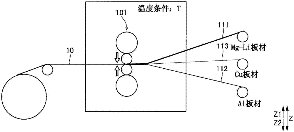
[0106] First, the cladding material 210 corresponding to Example 1 of the second embodiment described above was produced. Specifically, first, a Mg-Li sheet made of LZ91 (Mg-Li-Zn alloy), a pair of Al sheets made of A1080 (pure Al), and a pair of Cu sheets made of C1020 (pure Cu) were prepared. Among them, the specific gravity of LZ91 is 1.50, the specific gravity of A1080 is 2.70, and the specific gravity of C1020 is 8.94....


PUM

PropertyMeasurementUnit
peel strengthaaaaaaaaaa

Abstract

A cladding material (10) is provided with: a first layer (11) that is configured from an Mg-Li-based alloy; a second layer (12) that is configured from an Al-based alloy; and a first junction part (13) which is configured from a Cu-based alloy and is positioned on the junction interface (Ia) between the first layer and the second layer when viewed in cross section in the thickness direction. This cladding material has a specific gravity of 2.10 or less.

Description

technical field [0001] The present invention relates to a cladding material and an electronic device housing made of the cladding material. Background technique [0002] Currently, Mg (magnesium)-based alloys are known as lightweight materials used for housings and the like of portable terminals. However, Mg-based alloys have a problem of low corrosion resistance. Therefore, by fabricating a clad material in which a layer made of a Mg-based alloy and a layer made of an Al (aluminum)-based alloy are bonded, it is desired to obtain a material in which the weight is reduced by the Mg-based alloy and the corrosion resistance is improved by the Al-based alloy. [0003] However, when a clad material is produced by directly joining a layer composed of a Mg-based alloy and a layer composed of an Al-based alloy, a fragile intermetallic compound is precipitated at the bonding interface between the layers, and as a result, a gap between the layers may occur. The problem of easy separ...

Claims


Application Information

Patent Timeline
Patent Type & Authority Applications(China)
IPC IPC(8): B32B15/01B23K20/00B23K20/04C22C23/00H05K5/02C22F1/00C22F1/04C22F1/06
CPCC22C23/00C22F1/04C22F1/06B23K2103/12B23K2103/18B23K20/04B23K2103/15B23K2103/10B23K35/302B32B15/017B32B15/20B32B2457/00Y10T428/12347B32B15/01H05K5/04
Inventor 山本晋司井上良二
Owner PROTERIAL LTD
Why Eureka
Try Eureka