Joint component and method of manufacturing same

A technology for joining parts and manufacturing methods, applied in the direction of connecting components, manufacturing tools, clutches, etc., capable of solving problems such as unestimated flow paths, melting, etc.

Active Publication Date: 2017-11-28
AISIN AW CO LTD
View PDF6 Cites 3 Cited by
  • Summary
  • Abstract
  • Description
  • Claims
  • Application Information

AI Technical Summary

Problems solved by technology

[0005] However, in the conventional welding methods using high-energy beams including Patent Document 1, it is not estimated that there is a flow path in the butt joint to be welded in the base material at all.
Assuming that in the structure where there is a flow path in the butt part to be welded, in the case of the welding method of Patent Document 1, since the main welding is performed on the entire circumference of the butt part, the peripheral part of the flow path in the butt part is melted. concerns

Method used


Image

  • Joint component and method of manufacturing same
  • Joint component and method of manufacturing same
  • Joint component and method of manufacturing same

Examples


Embodiment 1

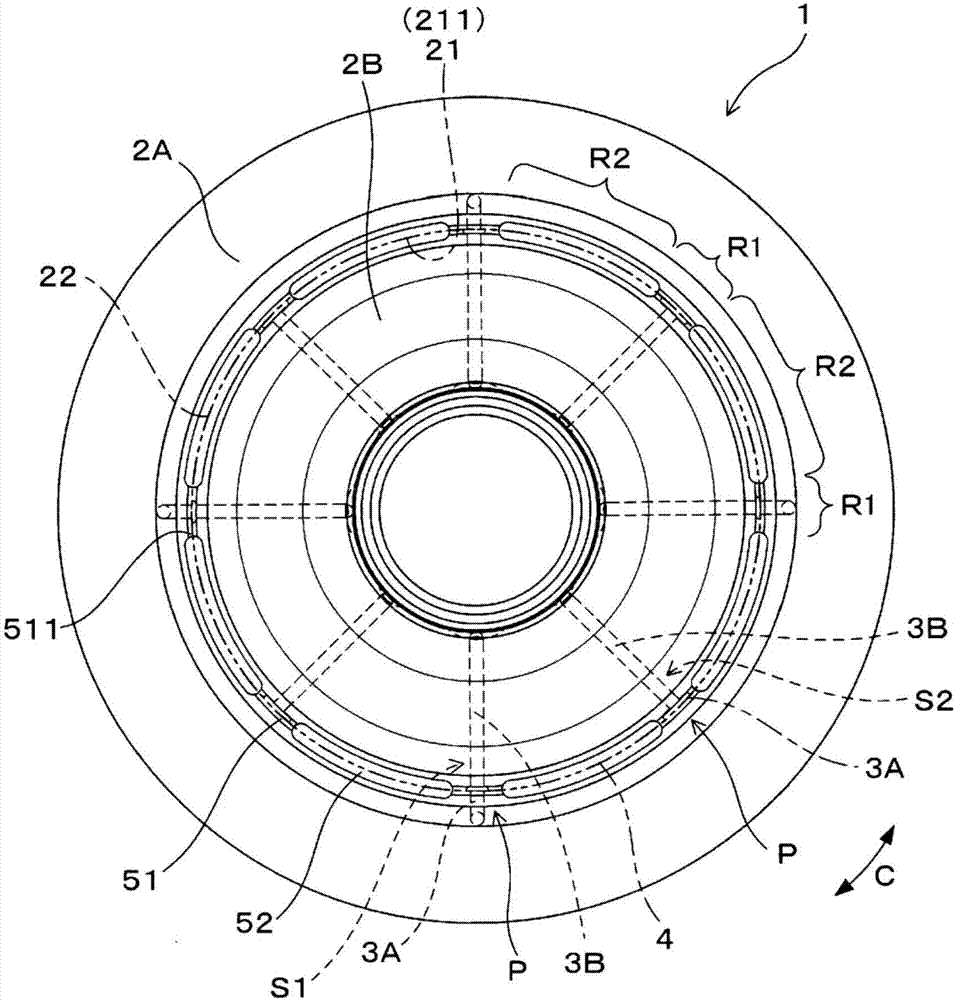
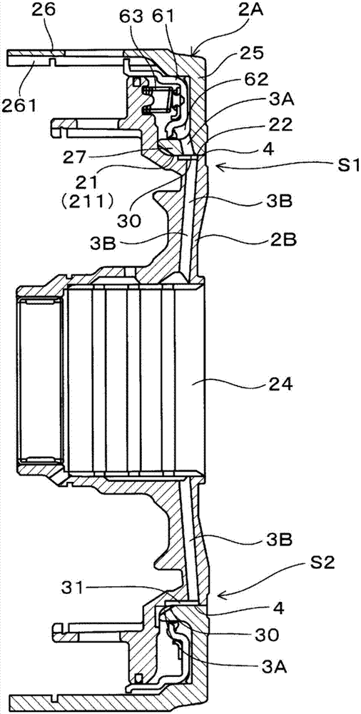
[0053] Such as figure 1 , figure 2 As shown, the joining member 1 of this example is composed of two metal sheets 2A, 2B welded to each other. The outer metal sheet 2A as the first metal sheet and the inner metal sheet 2B as the second metal sheet are joined by welding by irradiation of a high-energy beam on the joint surface 4 where the outer metal sheet 2A and the inner metal sheet 2B face each other. . In the outer metal sheet 2A, a first flow path 3A through which a fluid passes is provided at a certain depth from the surface 23 on the side irradiated with the high-energy beam. In the inner metal sheet 2B, a second flow path 3A through which a fluid passes is provided at a certain depth from the surface 23 on the side irradiated with the high-energy beam. The second flow path 3B is connected to the first flow path 3A at the junction surface 4 .

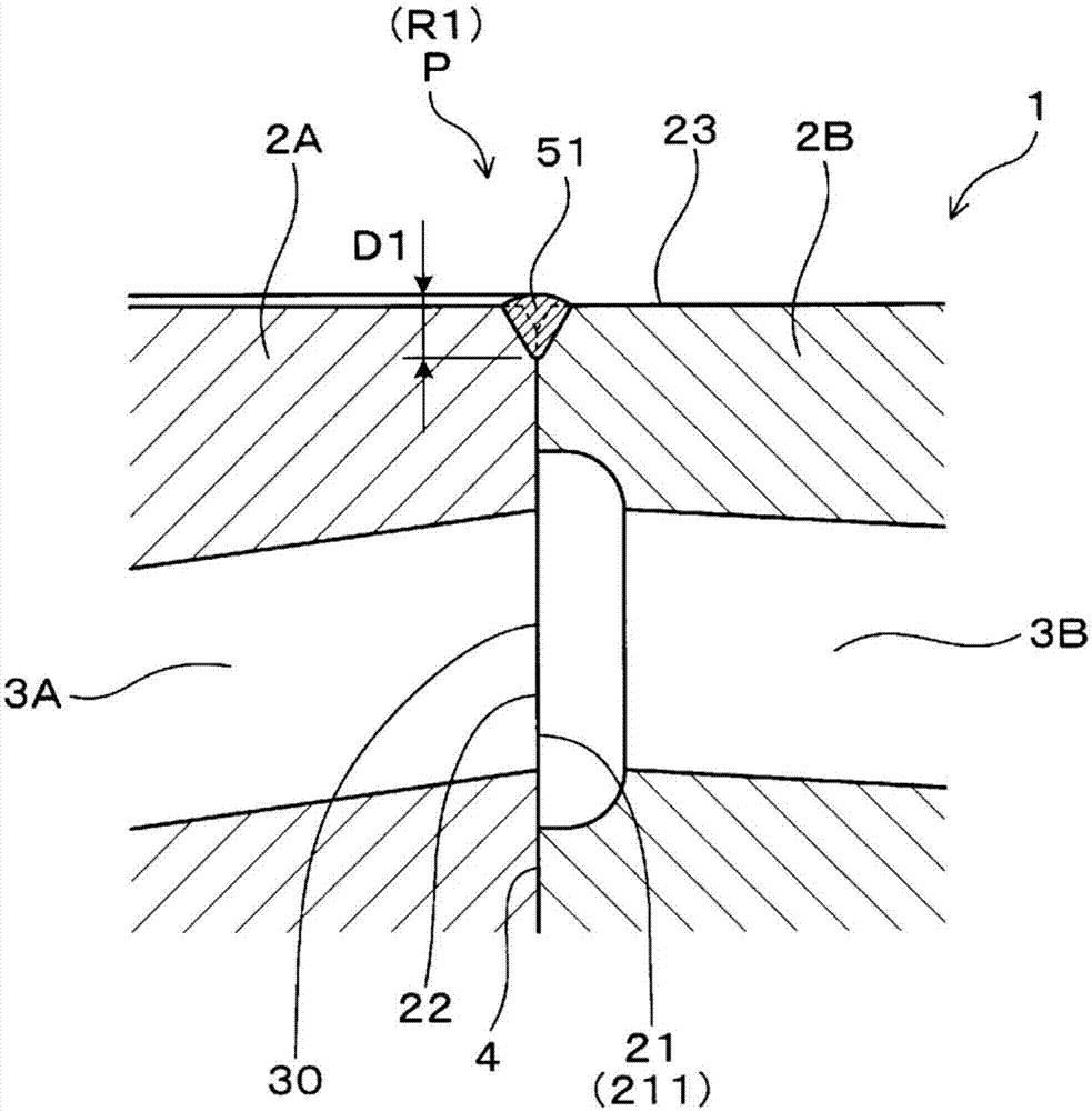
[0054] Such as image 3 As shown, the first range of the bonding surface 4 including the specific portion P overlapping th...

Embodiment 2

[0090] In this example, after the second welding is performed in the second range R2 with a penetration depth D2 that does not reach the first flow path 3A and the second flow path 3B, in the first range R1 the welding is performed without reaching the first flow path 3A and the second flow path. The penetration depth D1 of the road 3B is shown for the manufacturing method of the joined component 1 where the first welding is performed.

[0091] In this example, the first welding step shown in Example 1 was performed after the second welding step shown in Example 1 was performed.

[0092] In the case where the second welding step is performed after the first welding step shown in Example 1, the following problems may arise.

[0093] When the first welding is performed in the circumferential direction C of the joint surface 4 of the outer metal sheet 2A and the inner metal sheet 2B, the metal material is melted and resolidified near the surface 23 on the side irradiated with the...


PUM

PropertyMeasurementUnit
depthaaaaaaaaaa

Abstract

The objective of the present invention is to provide a joint component and a method of manufacturing the same, with which it is possible to protect a linking site between a first flow path and a second flow path, to prevent leakage of fluid from the first flow path and the second flow path, and to ensure the strength of a joint between a first metal piece and a second metal piece. In a joint component (1), a first flow path (3A) of an outside metal piece (2A) and a second flow path (3B) of an inside metal piece (2B) are linked together at a specific site (P) on a joining surface (4). A small bead portion (51) having a weld penetration depth that does not reach a linking site (30) is provided in a first region (R1) of the joining surface (4), including the specific site (P). A large bead portion (52) having a weld penetration depth that is greater than the weld penetration depth of the small bead portion (51) is provided in a second region (R2) excluding the first region (R1).

Description

technical field [0001] The present invention relates to a joining member composed of a plurality of metal sheets welded to each other and a method of manufacturing the same. Background technique [0002] When forming casings, covers, etc. of various mechanical parts, due to molding constraints and the like, high-energy beams such as electron beams and laser beams are sometimes used to weld a plurality of metal sheets (base materials). [0003] For example, in the laser butt welding method between metal pipes in Patent Document 1, a step of provisionally welding the butt joints with a depth of penetration shallower than the thickness of the pipes is performed, and the process of melting the pipes so as to penetrate the entire area in the direction of the pipe thickness is performed to weld the butt joints. week's work. [0004] Patent Document 1: Japanese Patent Application Laid-Open No. 10-272586 [0005] However, in the conventional welding methods using high-energy beams...

Claims


Application Information

Patent Timeline
Patent Type & Authority Applications(China)
IPC IPC(8): B23K15/00B23K15/04B23K26/28F16D13/60F16D25/0638
CPCB23K15/00B23K15/04B23K26/28F16D13/60F16D25/0638B23K2101/06F16D2250/0076F16D25/10B23K26/282B23K15/0053F16B5/08F16B7/00
Inventor 大野弘行青山哲也岩间崇宫元优友鸟居武史中岛启甫
Owner AISIN AW CO LTD
Why Eureka
Try Eureka