Copper wire and electrode joining method and joint structure

a copper wire and electrode technology, applied in non-electric welding apparatuses, manufacturing tools, welding/soldering/cutting articles, etc., can solve the problems of capillary damage to the electrode, cracks tend to develop in the cu, etc., to reduce the like, and ensure the strength of the joint. , the effect of reducing the likelihood of electrode damag

Active Publication Date: 2017-06-22
TOYOTA JIDOSHA KK
View PDF2 Cites 3 Cited by
  • Summary
  • Abstract
  • Description
  • Claims
  • Application Information

AI Technical Summary

Benefits of technology

[0009]According to this kind of structure, the rubbed portion is formed by rubbing the core wire that is covered with the coating against the electrode, so the coating remains between the electrode and the core wire. As a result, the core wire does not directly contact the electrode. Because the ball is joined to the rubbed portion, joint strength is able to be ensured while inhibiting mutual diffusion of the copper atoms in the core wire and the aluminum atoms in the electrode. Therefore, the formation of a Cu—Al compound layer between the copper wire and the electrode is able to be inhibited, so a decrease in the durability of the joint of the copper wire, and the electrode that includes Al as a main component is inhibited. The capillary is made of ceramic or the like, and is harder than the electrode and the like. Therefore, the capillary may damage the electrode and the like when joining only the electrode and the rubbed portion. However, with the structure described above, the copper wire and the electrode are able to be joined with less likelihood that the electrode and the like will be damaged by the capillary compared to when joining only the electrode to the rubbed portion, by joining the copper wire to the electrode by pressing the ball against the rubbed portion with the capillary.

Problems solved by technology

Cracks tend to develop in this Cu—Al compound layer.
Therefore, the capillary may damage the electrode and the like when joining only the electrode and the rubbed portion.

Method used


Image

  • Copper wire and electrode joining method and joint structure
  • Copper wire and electrode joining method and joint structure
  • Copper wire and electrode joining method and joint structure

Examples


Embodiment Construction

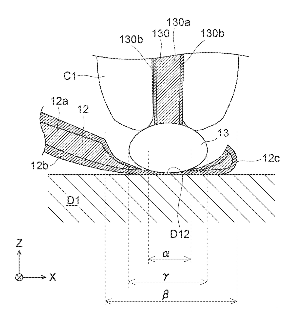
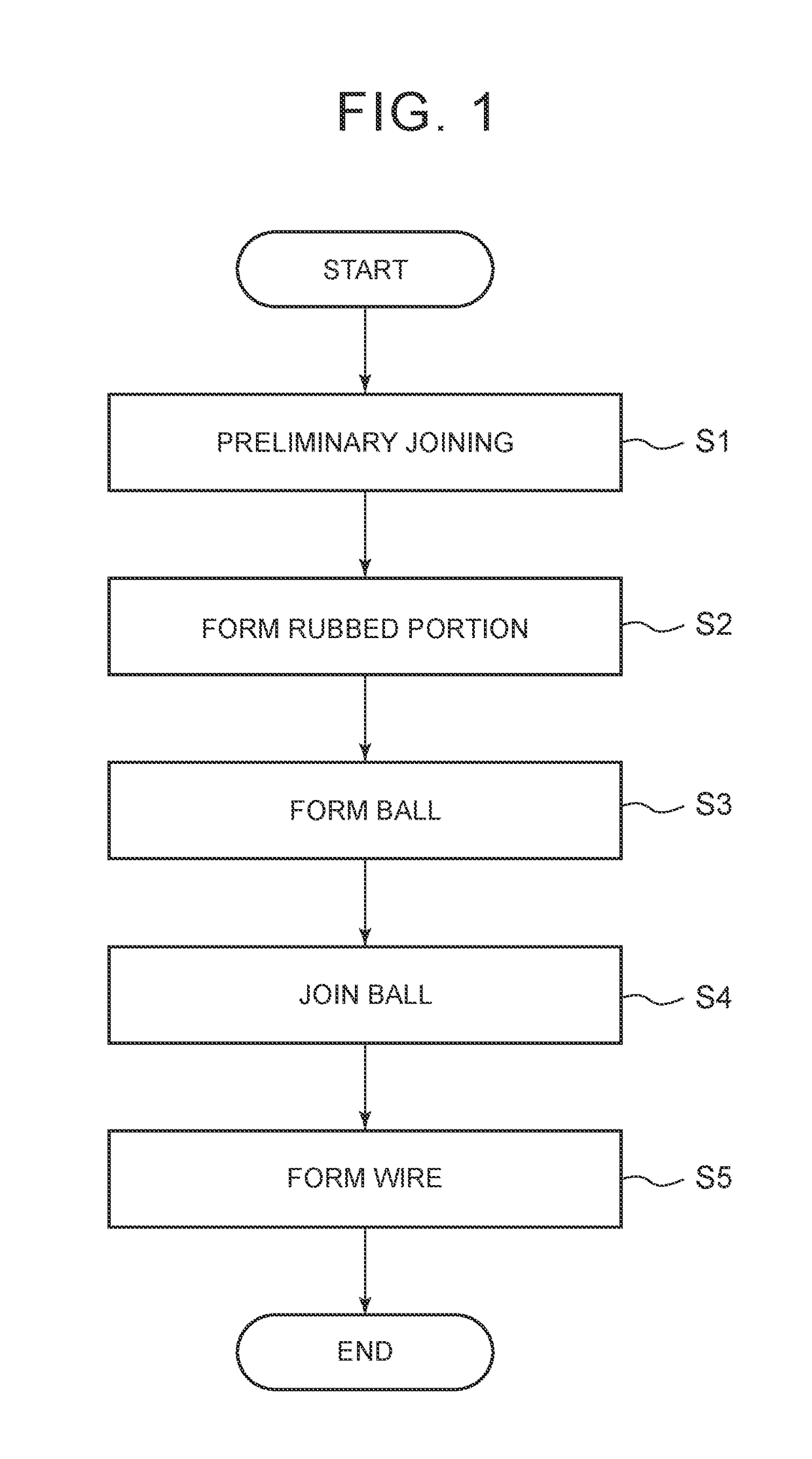
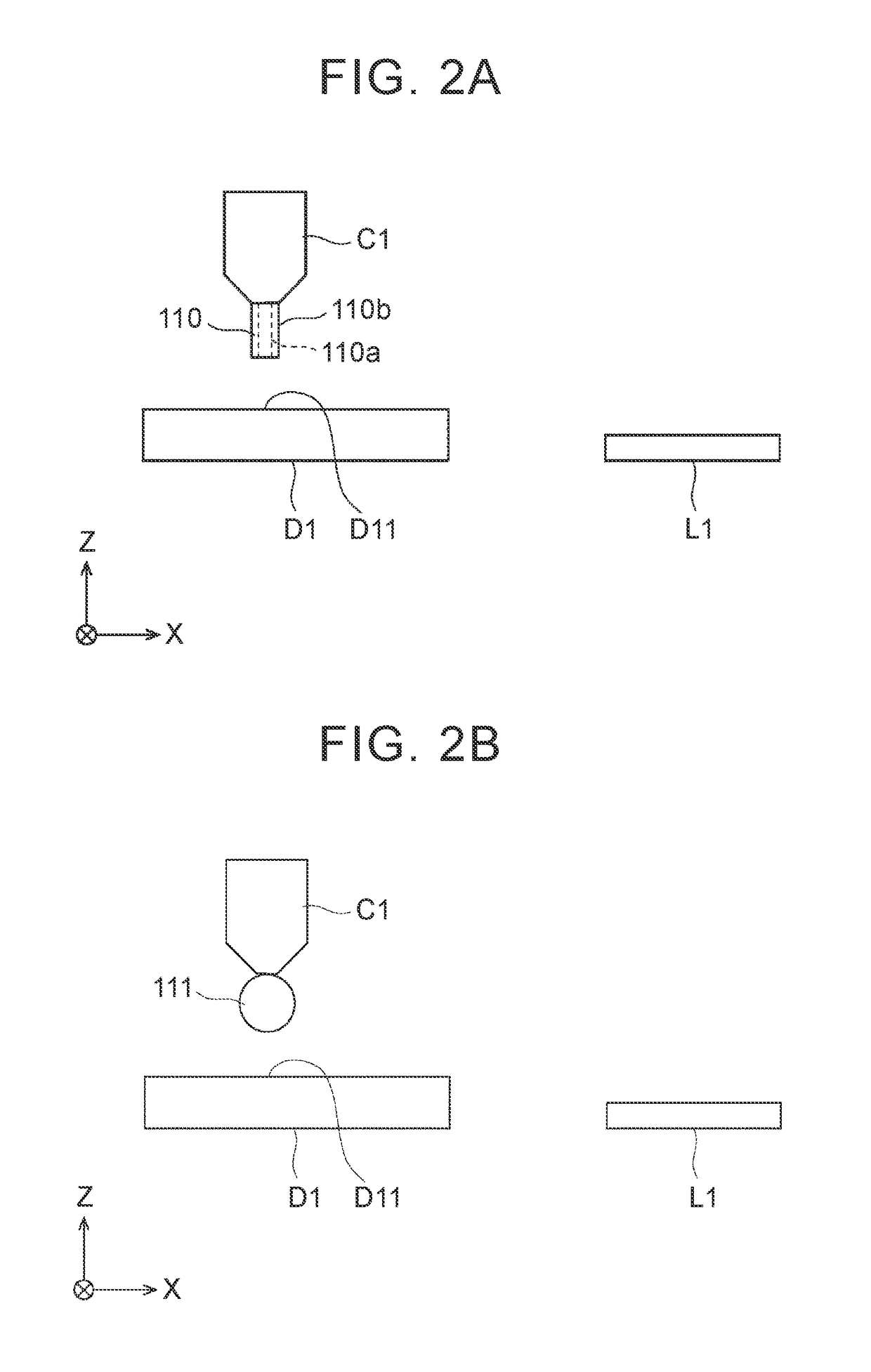
[0036]A copper wire joining method according to a first example embodiment will now be described with reference to FIGS. 1 to 3D. FIG. 1 is a flowchart illustrating a copper wire joining method according to the first example embodiment. FIGS. 2A to 2L are views showing frame formats of steps in the copper wire joining method according to the first example embodiment. FIGS. 3A to 3D are views showing frame formats of the details of the steps in the copper wire joining method according to the first example embodiment. In the drawings (FIGS. 2 to 9), a right-handed xyz three-dimensional coordinate system is provided as appropriate. The joining method of the first example embodiment connects a device-side electrode D1 to a lead frame-side electrode L1 using a copper wire. The device-side electrode D1 includes aluminum (Al) as its main component.

[0037]As shown in FIGS. 2B and 2C, a preliminary bond 11 is formed at a preliminary joining region D11 (preliminary joining step S1).

[0038]More ...


PUM

PropertyMeasurementUnit
distanceaaaaaaaaaa
joint structureaaaaaaaaaa
electrical resistanceaaaaaaaaaa

Abstract

With this copper wire joining method, a rubbed portion on which a coating remains between an electrode and a core wire is formed on the electrode. Then, after a capillary is moved away from the rubbed portion, and a ball is formed by melting a copper wire at a tip end of the capillary. Next, the ball is joined to the rubbed portion by pressing the ball against the rubbed portion.

Description

INCORPORATION BY REFERENCE[0001]The disclosure of Japanese Patent Application No. 2015-248573 filed on Dec. 21, 2015 including the specification, drawings and abstract is incorporated herein by reference in its entirety.BACKGROUND[0002]1. Technical Field[0003]The disclosure relates to a copper wire and electrode joining method and joint structure.[0004]2. Description of Related Art[0005]There is a copper wire in which a core wire that includes copper (Cu) as a main component is covered with a coating that includes a noble metal as a main component. This kind of copper wire is described in Japanese Patent Application Publication No. 62-097360 (JP 62-097360 A), for example, and inhibits oxidation of the core wire, as well as a decrease in bondability.SUMMARY[0006]This kind of copper wire is sometimes joined to an electrode that includes aluminum (Al) as a main component using ball bonding. When ball bonding is performed with this kind of joining, the coating and the core wire melt alm...

Claims


Application Information

Patent Timeline
Patent Type & Authority Applications(United States)
IPC IPC(8): H01L23/00
CPCH01L24/85H01L24/48H01L2224/85047H01L2924/30101H01L2224/48824H01L2224/48453H01L2924/35121H01L2224/85035B23K20/007B23K20/10B23K20/2333B23K2101/32B23K2101/36B23K2103/10B23K2103/12B23K2103/18H01L24/45H01L24/49H01L2224/05553H01L2224/05624H01L2224/45147H01L2224/45565H01L2224/45639H01L2224/45644H01L2224/45664H01L2224/45669H01L2224/45676H01L2224/48465H01L2224/78301H01L2224/85045H01L2224/85051H01L2224/85181H01L2224/85986H01L2924/00014
Inventor SATO, YOH
Owner TOYOTA JIDOSHA KK
Why Eureka
Try Eureka