Method and apparatus for trimming a sample from a coiled metal web

a technology of coiled metal and end pieces, which is applied in the field of trimming end pieces from coiled metal coils, can solve the problems of preventing further rotational maneuvering and remaining edges on the coils, and achieve the effect of preventing deformation of the coil material dimensions and facilitating rebanding of the coils

Active Publication Date: 2012-07-26
PRIMETALS TECH USA
View PDF2 Cites 18 Cited by
  • Summary
  • Abstract
  • Description
  • Claims
  • Application Information

AI Technical Summary

Benefits of technology

[0006]Accordingly, embodiments of the present invention include the creation a coil trimming and sampling system that, in one aspect reduces and in yet another prevents deformation of the coil material dimensions during the trimming or sampling procedure, and facilitates rebanding of the coil in its taut, fully coiled state.
[0007]Another embodiment of the present invention includes a coil trimming and sampling system that facilitates a clean separation of the coil sample from the coil while minimizing localized coil material dimensional deformation along the separation edge.
[0008]An additional embodiment of the present invention includes a coil trimming and sampling system that facilitates passage of the separation edge remaining on the coil over the rollers as the coil is manipulated, including for re-strapping the coil in it tensioned wrapped state.
[0011]In embodiments of the present invention, cut channel depth and angle may be selected so that the trimmed / sampled end's full material thickness is not penetrated. The uncut necked material thickness remaining at the depth of the cut channel formation is selected to allow a clean separation of the material. Angular cutting reduces deformation of the material along the edge remaining on the coil and reduces the force required to separate the strip downstream the cut channel. If the separation force is less than the material's tensile strength there is less likelihood that the edge will be deformed. After sample extraction the coil maintains rolled tautness for ease of rebanding.
[0012]Embodiments of the present invention include sampling systems for extracting a sample from an end strip of a coil having wrapped layers of coiled formed elongated metal. The system has a pair of generally parallel spaced drive rollers that are driven by a roller drive system coupled thereto, for selective rotation of a coil about a coil central axis that is oriented parallel to the rollers. A cutter is proximal the rollers for alignment with a circumference of a metal coil resting on the driven rollers. The cutter has a cutter drive mechanism for selectively advancing the cutter into the coil and selectively traversing the cutter along the coil circumference. A coil tensioner mechanism maintains tension on wrapped layers against each other in a metal coil resting on the rollers, in order to inhibit relaxation of the coiled layers.
[0013]Embodiments of the present invention additionally include a method for extracting a sample form an end strip of a coil having wrapped layers of coiled formed elongated metal with a sampling system. The method is performed by placing a banded coil, having a central axis, on a pair of generally parallel spaced driven rollers so that the coil central axis is oriented parallel to the driven rollers. Tension is maintained between wrapped layers in the coil against each other with a coil tensioner, so that the coil can be unbanded without disturbing the tensioned layers. The coil is rotated with the driven rollers so that a desired length of end strip is oriented downstream the cutter. The end strip material is cut by selectively advancing and traversing the cutter into the coil in any desired sequence. The end strip is then extracted from the coil.

Problems solved by technology

The sheared edge remaining on the coil may have localized distortion and a relatively blunt edge generally along the coil's radial circumference that may hinder further rotational maneuvering of the coil on the rollers.

Method used


Image

  • Method and apparatus for trimming a sample from a coiled metal web
  • Method and apparatus for trimming a sample from a coiled metal web
  • Method and apparatus for trimming a sample from a coiled metal web

Examples


Embodiment Construction

[0029]After considering the following description, those skilled in the art will clearly realize that the teachings of my invention can be readily utilized in coiled metal sample extraction systems and methods.

[0030]General System Overview

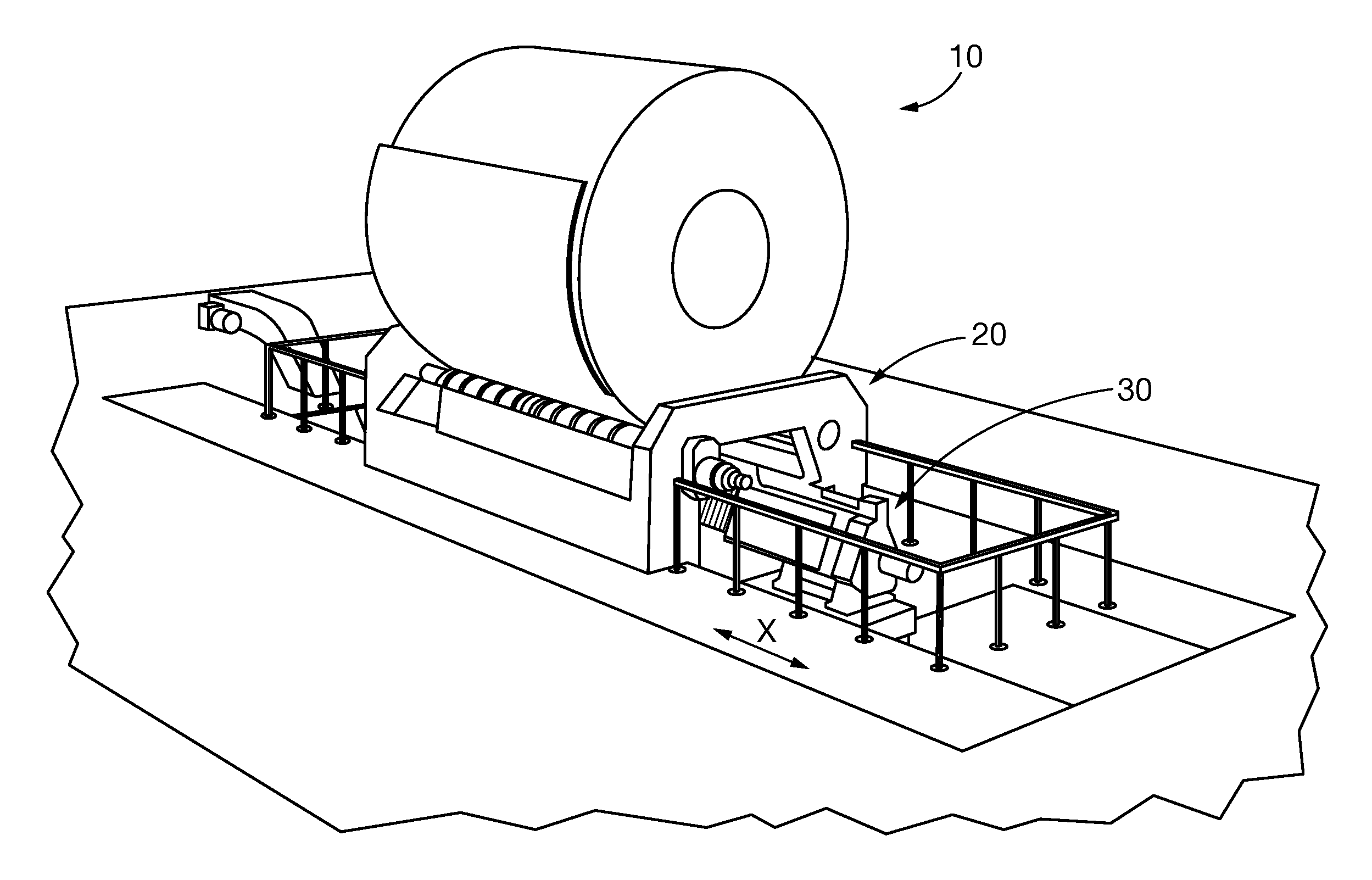
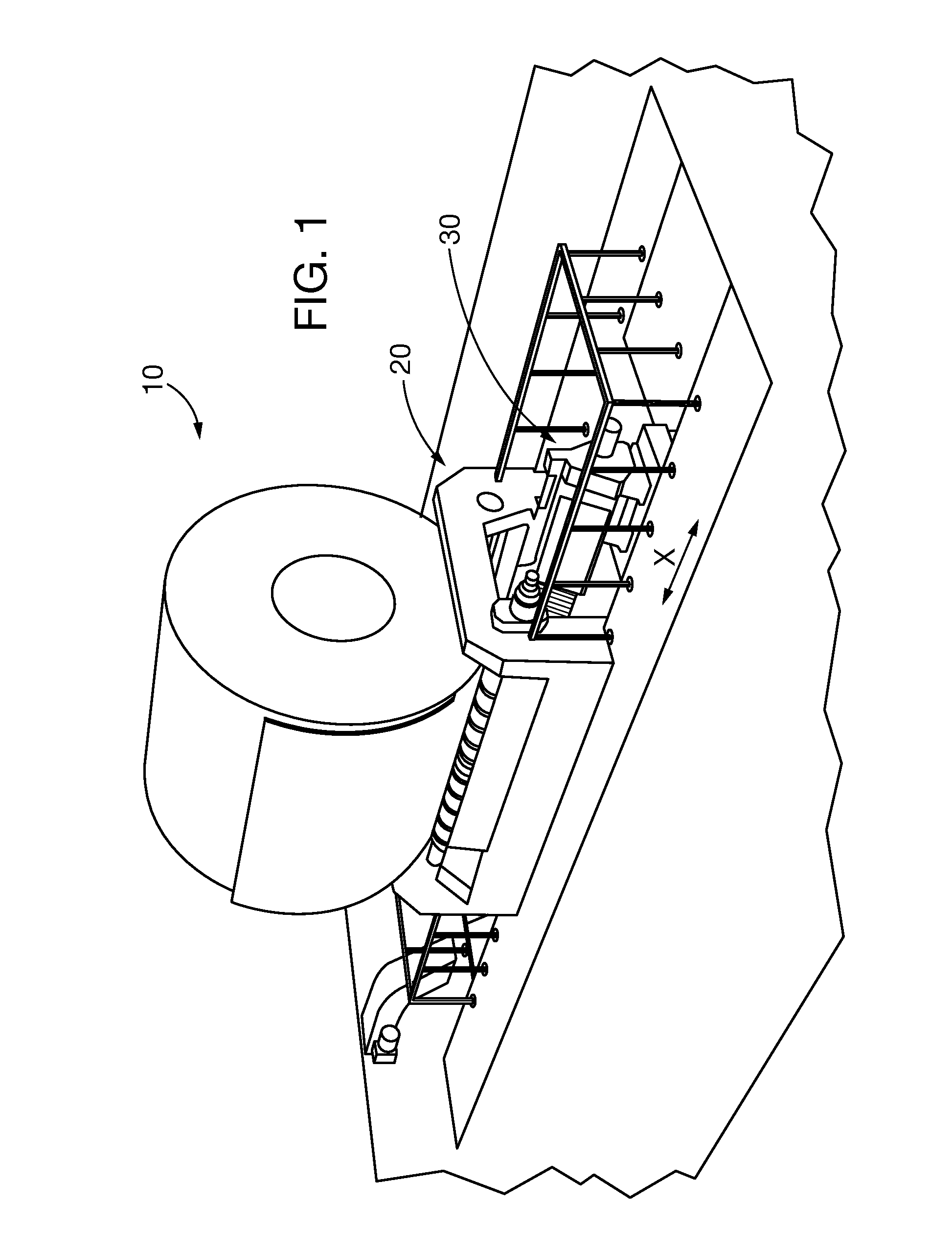
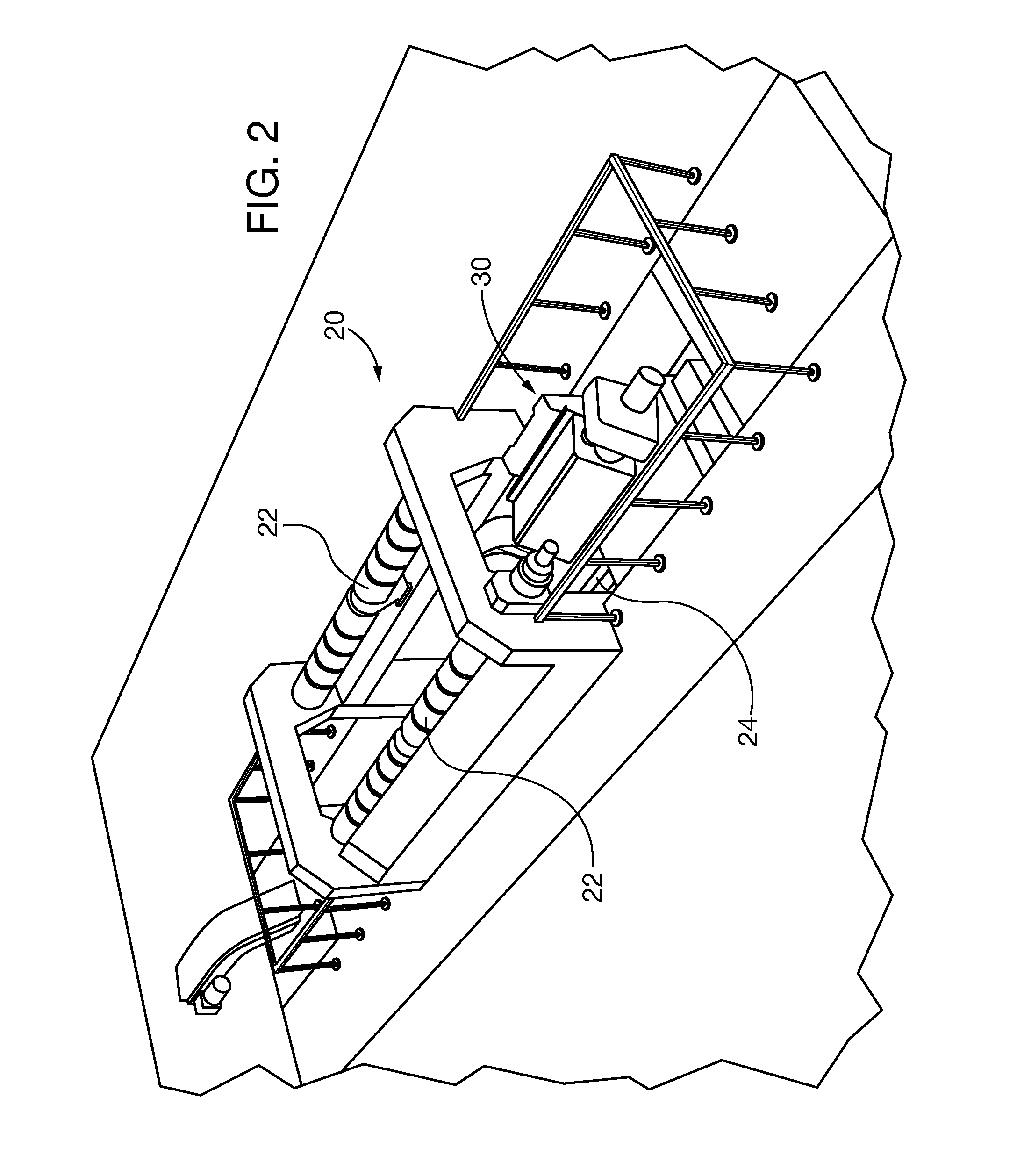
[0031]Referring generally to FIGS. 1 and 2, showing one exemplary embodiment of the present invention, a coiled metal web 10 is placed in a sample extraction system 20, where it rests on at least a pair of driven rollers 22, in an exemplary embodiment there are two driven rollers as illustrated in FIGS. 1 and 2, that are capable of causing rotation of the coil about its central rotational axis. While coiled sheet web is shown in the figures herein, other types of elongated coiled formed metal may be accommodated in the sampling system of the present invention, including by way of nonlimiting example rebar, round or rectangular barstock, pipe and tubing. A sample cutter 30 can be positioned parallel to and between the rollers 22, as well as the coil...


PUM

PropertyMeasurementUnit
thicknessaaaaaaaaaa
cut angleaaaaaaaaaa
diameteraaaaaaaaaa

Abstract

Sample extraction or trimming from an end strip of an elongated formed metal that is coiled in layers within a tensioned metal coil resting on driven rollers. A cut channel is formed across the material width. In some embodiments the cut channel is formed between the rollers and by cutting at an angle relative to the coil outer surface. Coil weight and / or a coil tensioner mechanism inhibits coil relaxation along the cut channel by maintaining tension on wrapped layers against each other when the coil is unbanded for sample extraction. The coil is rotated so that the cut channel clears the rollers laterally. Material downstream the cut is then separated from the coil. After trimming and / or sample extraction the coil maintains rolled tautness for ease of rebanding.

Description

CLAIM TO PRIORITY[0001]This application claims the benefit of two co-pending United States provisional patent applications, respectively entitled: “Automated Heavy Gauge Sampling Station”, filed, Jan. 20, 2011, and assigned Ser. No. 61 / 434,630 and “Method and Apparatus for Trimming a Sample from a Coiled Metal Web”, filed, May 23, 2011, and assigned Ser. No. 61 / 488,874; both of which are incorporated by reference herein.BACKGROUND[0002]1. Field[0003]Embodiments of the present invention relate to trimming ends from a coil of coiled formed metal without distorting the material remaining on the coil and maintaining the coil layers tightly wrapped in taut tension for banding or rebanding. Coil ends are trimmed for obtaining test and inspection samples, as well as for trimming scrap tail ends.[0004]2. Description of the Prior Art[0005]A known system places a banded metal coil of tightly wrapped formed elongated sheet material (e.g., a sheet web) between spaced parallel rollers, removes b...

Claims


Application Information

Patent Timeline
Patent Type & Authority Applications(United States)
IPC IPC(8): B23Q5/00B23D37/22B26D3/00B23K10/00B26D3/06B23D31/00B23H1/00B23C3/12B23P17/00
CPCB21C47/24B21C51/00G01N1/04Y10T409/303808Y10T409/4035Y10T409/400175Y10T409/306048Y10T83/0304Y10T83/04Y10T83/0448Y10T83/6667
Inventor GRZYB, JENNIFERSALPECK, PATRICKWALNOHA, LEN
Owner PRIMETALS TECH USA
Why Eureka
Try Eureka